Overview
This page lists the key performance parameters of each AXRY-EX size: the axial and radial dynamic and static load ratings, the rigidity of the bearing position (axial, radial and tilting), and the limiting speed.
Nominal life time
The nominal life time is calculated by myonic using special calculation programs. You are welcome to request our technical questionnaire by writing to sales@eb-system.com, and our application engineering team will perform the calculation for you. The following data is required for the calculation:
- Details on the application (drawings, sketches, specifications)
- Workpiece dimensions and weight
- Details on the load cycle (cutting forces, speeds, operating durations)
Static load safety factor
The static load safety factor S0 must be calculated separately for the radial and axial bearing parts, using the following formulas:
S0 = C0a / F0a or S0 = C0r / F0r
For machine tool applications, a value of S0 ≥ 4 is recommended.
Static limiting load diagrams
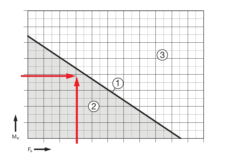
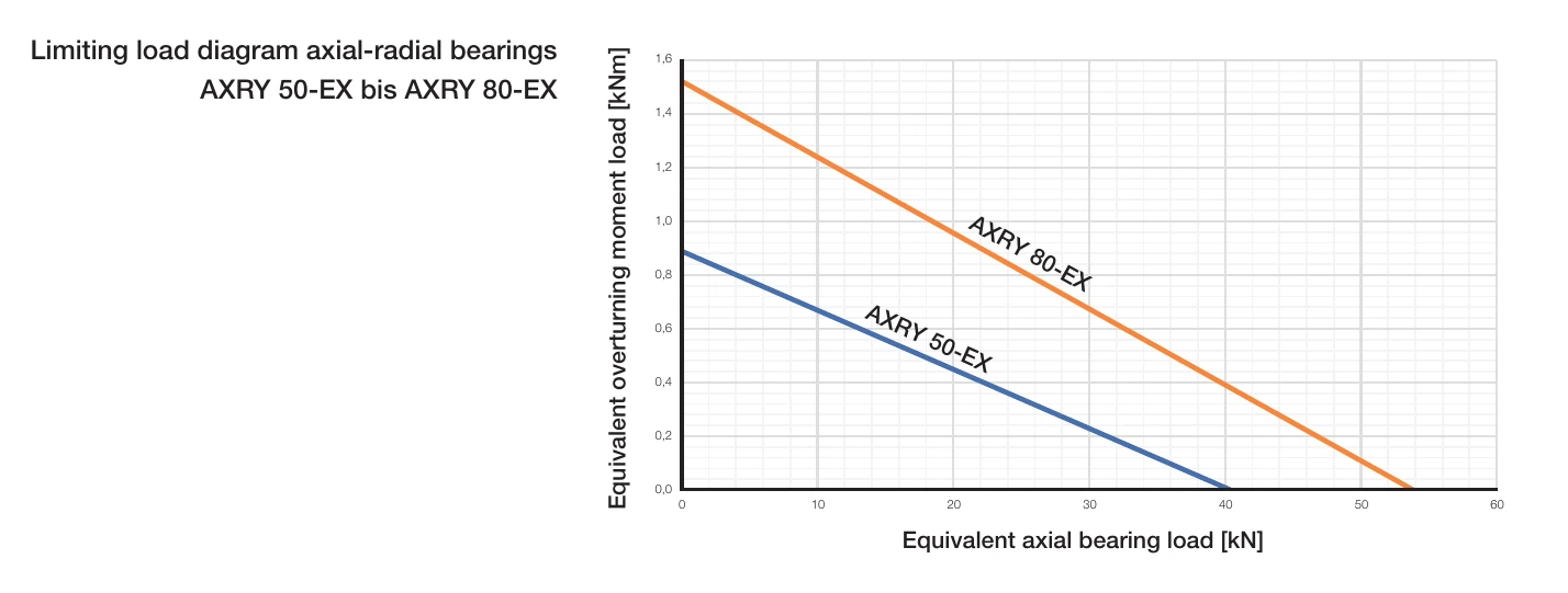
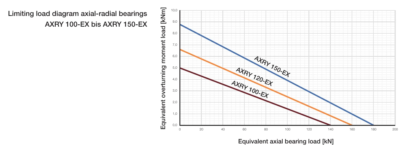
The static limiting load diagrams serve to: (1) check the selected bearing size under mainly static load; and (2) determine the tilting moment MK which the AXRY is able to absorb in addition to the axial load. The diagrams already take into account, for the roller element set, the static load safety factor S0 ≥ 4 as well as the screw and bearing ring strength.
- 1: Bearing/size curve / 2: Permitted range / 3: Unpermitted range
- MK: Maximum tilting moment [kNm] / Fa: Axial load [kN]
Load ratings and rigidity overview
- Ca: Dynamic axial load rating [kN]
- C0a: Static axial load rating [kN]
- Cr: Dynamic radial load rating [kN]
- C0r: Static radial load rating [kN]
- nG: Limiting speed, grease [rpm]
- MRL: Bearing friction torque (reference value, grease) [Nm]
- Cal: Axial rigidity of bearing position [kN/μm]
- Crl: Radial rigidity of bearing position [kN/μm]
- Ckl: Tilting rigidity of bearing position [kNm/mrad]
- Rmin: Minimum corner radius [mm]
| Designation | Axial load rating | Radial load rating | nG [rpm] | MRL [Nm] | Rigidity of bearing position | Rmin [mm] | ||||
|---|---|---|---|---|---|---|---|---|---|---|
| Ca [kN] | C0a [kN] | Cr [kN] | C0r [kN] | Cal [kN/μm] | Crl [kN/μm] | Ckl [kNm/mrad] | ||||
| AXRY 50-EX | 33.5 | 161.6 | 22.7 | 39.2 | 2000 | 1.5 | 2.4 | 1.2 | 2.5 | 0.6 |
| AXRY 80-EX 4) | 39.5 | 215.4 | 51.0 | 104.9 | 1500 | 2.0 | 3.0 | 1.9 | 4.9 | 0.6 |
| AXRY 100-EX 4) | 89.2 | 560.6 | 56.3 | 126.9 | 1300 | 2.0 | 4.1 | 2.4 | 10.0 | 0.8 |
| AXRY 120-EX | 95.3 | 640.6 | 62.1 | 152.9 | 1150 | 4.5 | 4.8 | 3.0 | 16.3 | 0.8 |
| AXRY 150-EX | 100.4 | 720.7 | 68.4 | 185.0 | 1000 | 7.0 | 5.4 | 3.7 | 25.1 | 0.8 |
4) Screw counterbores in large L-ring open to bearing bore. Bearing inside diameter is not supported in this area.
MRL is a reference value: measuring speed nconst = 5 min-1; with myonic standard grease and standard grease quantity; without support ring; the friction torque can increase up to 2.5 times up to the limiting speed.
Axial runout and radial runout
- PL: Preload
- RL: Clearance
- Standard: Standard accuracy (axial and radial runout) [μm]
- Restricted: Restricted accuracy (axial and radial runout) [μm]
| Designation | Axial runout & radial runout [μm] | |
|---|---|---|
| Standard PL & RL | Restricted PL & RL | |
| AXRY 50-EX | 2 | 1 |
| AXRY 80-EX 4) | 3 | 1.5 |
| AXRY 100-EX 4) | 3 | 1.5 |
| AXRY 120-EX | 3 | 1.5 |
| AXRY 150-EX | 3 | 1.5 |
Runout values measured on a bearing installed in ideal adjacent construction.
Important notes
- Dynamic load: Under dynamic operating conditions, the dynamic load ratings (Ca, Cr) must be used for the life time calculation.
- High speed applications: For applications exceeding the limiting speed nG, please consult sales@eb-system.com separately.
- Effect of preload: Preload reduces the available external load capacity while increasing rigidity.
- Mounting errors: Mounting errors generate additional internal loads in the bearing and should be included in the design assessment.