Type Designation
L7 motor designations are composed of series name, primary part length, and secondary part width (e.g. L7-3P-...-300 in the geometric drawing where ... stands for the length-width pair).
L7-3P-{length}-{width}
- L7 — series code (high-efficiency water-cooled iron-core linear motor)
- 3P — three-phase
- length — primary part length (mm):
350/500/650 - width — secondary part width (mm):
100/150/200/300
Catalogue size shorthand
The 350-100 form used in this catalogue is the "length-width" shorthand, equivalent to L7-3P-350-100. For example, 650-300 refers to the largest L7 model with 650 mm primary part length and 300 mm secondary part width.
Winding Codes
Each L7 model is paired with a specific winding design. The following winding codes appear in this series:
| Winding Code | Applicable Models |
|---|---|
| Z1.9H | 350-100, 350-150 |
| Z2.7H | 650-100, 650-150 |
| Z2.8H | 500-100, 500-150, 350-200, 500-200, 350-300, 500-300 |
| Z3.8H | 650-200, 650-300 |
Force, Current & Velocity Symbols
| Symbol | Unit | Definition |
|---|---|---|
| Fu | N | Ultimate force (1 s) at Iu eff |
| Fp | N | Peak force at Ip eff |
| Fcw | N | Continuous force (cooled) at Icw eff |
| Fc | N | Continuous force (not cooled) at Ic eff |
| Fsw | N | Stall force (cooled) at Isw eff |
| Fcog | N | Cogging force at I = 0 |
| Fa | N | Attraction force |
| Iu eff | A | Effective ultimate current (1 s) |
| Ip eff | A | Effective peak current |
| Icw eff | A | Effective continuous current (cooled) |
| Ic eff | A | Effective continuous current (not cooled) |
| Isw eff | A | Effective stall current (cooled) |
| vlp600 | m/s | Limiting velocity at Ip eff and UDCL = 600 V |
| vlw600 | m/s | Limiting velocity at Icw eff and UDCL = 600 V |
| vlp300 | m/s | Limiting velocity at Ip eff and UDCL = 300 V |
| vlw300 | m/s | Limiting velocity at Icw eff and UDCL = 300 V |
Power, Electrical & General Parameters
| Symbol | Unit | Definition |
|---|---|---|
| Plp | W | Power loss at Fp |
| Plw | W | Power loss at Fcw |
| Plc | W | Power loss at Fc |
| UDCL | V | DC link voltage (L7 standard 800 V) |
| R20 | Ω | Electrical resistance, phase to phase (20 °C) |
| L | mH | Inductance, phase to phase |
| kû | V/(m/s) | Back EMF constant, phase to phase |
| 2τp | mm | Pole pair width (46 mm across the entire L7 series) |
| km | N/√W | Motor constant (20 °C) |
| kf | N/A | Force constant |
| JPTC | °C | Motor temperature switch-off threshold (110 °C across the entire L7 series) |
Cooling Conditions Symbols
Reference medium: water at supply temperature 20 °C.
| Symbol | Unit | Definition |
|---|---|---|
| dV/dt | l/min | Recommended volume flow rate |
| ΔJ | K | Cooling water temperature difference |
| Δp | bar | Pressure drop |
Geometric Symbols
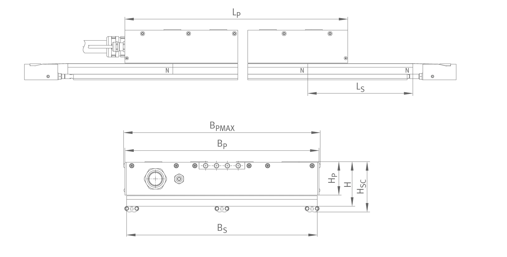
L7 side / end-view dimensions (Source: PHL en-GB / DE / 2025-01, p.8)
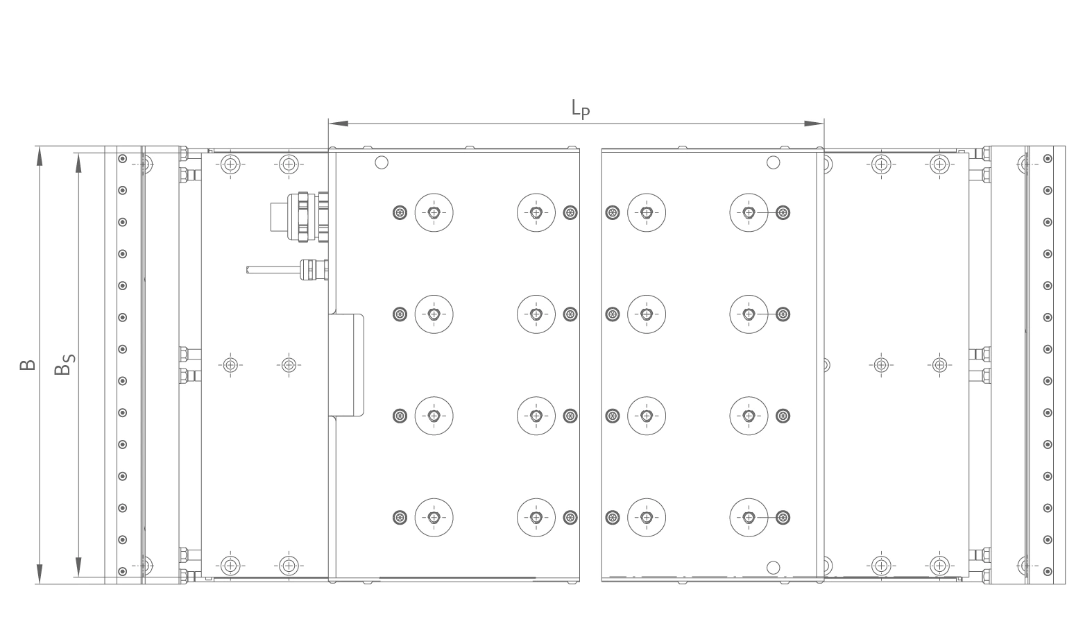
L7 top-view dimensions (Source: PHL en-GB / DE / 2025-01, p.8)
| Symbol | Subject | Definition |
|---|---|---|
| LP | Primary part | Length |
| BP | Primary part | Width |
| HP | Primary part | Height (58.5 mm across the entire L7 series) |
| BPMAX | Primary part | Maximum width |
| TSPC | Primary part | Cooling water connection (G 1/8″ female thread) |
| mP | Primary part | Mass |
| LS | Secondary part | Length (184 mm across the entire L7 series) |
| BS | Secondary part | Width |
| HS | Secondary part | Height (without encapsulation) |
| HSP | Secondary part | Height (encapsulated) |
| B | Installation | Width with secondary part cooling system |
| H | Installation | Height without secondary part cooling system |
| HSC | Installation | Height with secondary part cooling system |