MR Size 45 Technical Specifications
High load capacity with excellent rigidity
Rail Types MR S 45
| MR S 45-N | MR S 45-ND | MR S 45-NU | MR S 45-C |
|---|---|---|---|
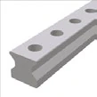 | 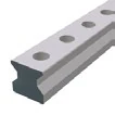 |  |  |
| Standard Top mounting | Standard, through-hardened Through-hardened | Bottom tapped holes Bottom mounting | Center clamping Center clamping |
Rail Dimensional Drawing MR S 45

Rail Specifications MR S 45
| Parameter | MR S 45-N | MR S 45-ND | MR S 45-NU | MR S 45-C |
|---|---|---|---|---|
| Rail Width B1 (mm) | 45 | 45 | 45 | 45 |
| Rail Height J1 (mm) | 40 | 40 | 40 | 40 |
| Max Single Length L3 (mm) | 6000 | 1500 | 6000 | 6000 |
| Fixing Hole Pitch L4 (mm) | 52.5 | 52.5 | 52.5 | 52.5 |
| First/Last Hole Position L5/L10 (mm) | 25 | 25 | 25 | 25 |
| Unit Weight (kg/m) | 10.8 | 10.8 | 11.8 | 10.6 |
Model Description
- N = Standard (top mounting)
- ND = Standard, through-hardened
- NU = Bottom tapped holes (bottom mounting)
- C = Center clamping
Carriage Types MR W 45
| MR W 45-A | MR W 45-B | MR W 45-C | MR W 45-D | MR W 45-F | MR W 45-G |
|---|---|---|---|---|---|
 |  |  |  |  |  |
| Standard Standard | Standard long Standard long | High/flat High/flat | High/flat long High/flat long | Flat Flat | Flat long Flat long |
Carriage Dimensional Drawing MR W 45

Carriage Specifications MR W 45
| Parameter | MR W 45-A | MR W 45-B | MR W 45-C | MR W 45-D | MR W 45-F | MR W 45-G |
|---|---|---|---|---|---|---|
| System Height A (mm) | 60 | 60 | 70 | 70 | 60 | 60 |
| Carriage Width B (mm) | 120 | 120 | 86 | 86 | 86 | 86 |
| Reference Surface Distance B2 (mm) | 37.5 | 37.5 | 20.5 | 20.5 | 20.5 | 20.5 |
| Front Center Lube Hole Position C1 (mm) | 8 | 8 | 18 | 18 | 8 | 8 |
| Side Lube Hole Position C3 (mm) | 8 | 8 | 18 | 18 | 8 | 8 |
| Side Lube Hole Position C4 (mm) | 21.25 | 38.75 | 31.25 | 38.75 | 31.25 | 38.75 |
| Top Lube Hole Position C7 (mm) | 17 | 34.5 | 27 | 34.5 | 27 | 34.5 |
| Carriage Height J (mm) | 50 | 50 | 60 | 60 | 50 | 50 |
| Carriage Length L (mm) | 145 | 180 | 145 | 180 | 145 | 180 |
| Cross Wiper Distance La (mm) | 140 | 175 | 140 | 175 | 140 | 175 |
| Outer Fixing Hole Pitch L1 (mm) | 80 | 80 | 60 | 80 | 60 | 80 |
| Inner Fixing Hole Pitch L2 (mm) | 60 | 60 | — | — | — | — |
| Steel Body Length L6 (mm) | 100 | 135 | 100 | 135 | 100 | 135 |
| Side Fixing Hole Pitch N (mm) | 100 | 100 | 60 | 60 | 60 | 60 |
| Reference Surface Height O (mm) | 10 | 10 | 10 | 10 | 10 | 10 |
| Carriage Weight (kg) | 3.2 | 4.3 | 3.0 | 4.0 | 2.3 | 3.1 |
Rigidity Curves and Load Rating Diagrams

Load Ratings
| Carriage Type | C₀ Static Load (N) | C₁₀₀ Dynamic Load (N) | M₀Q Static Cross Moment (Nm) | M₀L Static Long. Moment (Nm) | MQ Dynamic Cross Moment (Nm) | ML Dynamic Long. Moment (Nm) |
|---|---|---|---|---|---|---|
| A / C / F | 167,500 | 93,400 | 4,621 | 2,790 | 2,577 | 1,556 |
| B / D / G | 229,500 | 127,800 | 6,333 | 5,161 | 3,527 | 2,874 |
Load Rating Description
- C₀ = Static load capacity
- C₁₀₀ = Dynamic load capacity - 100km travel life
- M₀Q / MQ = Cross moment
- M₀L / ML = Longitudinal moment
Available Options
Accuracy Classes
| Accuracy Class | Carriage & Rail Tolerance A/B2 | Matched Carriage Max Difference ΔA/ΔB2 | Standard Carriage Max Difference |
|---|---|---|---|
| G0 Highly accurate | ± 5 µm | 3 µm | 10 µm |
| G1 Very accurate | ± 10 µm | 5 µm | 20 µm |
| G2 Accurate | ± 20 µm | 7 µm | 40 µm |
| G3 Standard | ± 30 µm | 25 µm | 60 µm |
Preload Classes
| Preload Class | Preload Force (% of C₀) | Application |
|---|---|---|
| V0 Very light preload | 0-2% | Very low friction, uniform load, minimum vibration |
| V1 Light preload | 3% | Low friction, uniform load, slight vibration |
| V2 Medium preload | 8% | High rigidity, moderate varying loads and vibration |
| V3 High preload | 13% | Maximum rigidity, impact loads, severe varying loads |
Lubrication Connections


| Code | Position | Description |
|---|---|---|
| S10 | Left center | Front plate left center position |
| S11 | Top center | Carriage top center |
| S12 | Top left | Carriage top left side |
| S13 | Lower left side | Carriage left side lower |
| S20 | Right center | Front plate right center position |
| S21 | Rear center | Rear plate center position |
| S22 | Top right | Carriage top right side |
| S23 | Lower right side | Carriage right side lower |
| S32 | Upper left side | Carriage left side upper |
| S42 | Upper right side | Carriage right side upper |
| S98 | Special | As per customer requirements |
| S99 | Special | As per customer requirements |
Lubrication as Delivered
| Code | Type | Description | Application |
|---|---|---|---|
| LN | Oil protect | Light oil coating | Applications with continuous oil supply after installation |
| LG | Grease protect | Thin grease layer | Applications with continuous grease supply after installation |
| LV | Full greasing | Complete grease filling | Applications with manual lubrication |
Coating
| Code | Type | Features |
|---|---|---|
| — | Standard (no coating) | Standard steel surface |
| CN | Hard chromium | Excellent corrosion resistance, high wear resistance, good emergency running properties |
Reference Side
R1 - Reference at bottom R2 - Reference on top
Order Code Examples
Rail Order Code
MR S 45-N-G1-KC-R1-1200-25-25-CN
- MR S 45 = MONORAIL Rail Size 45
- N = Standard type
- G1 = Very accurate
- KC = Fixing holes with countersink
- R1 = Reference at bottom
- 1200 = Rail length 1200mm
- 25-25 = First/last hole positions
- CN = Hard chromium coating
Carriage Order Code
MR W 45-B-G1-V2-R1-CN-S11-LV
- MR W 45 = MONORAIL Carriage Size 45
- B = Long carriage type
- G1 = Very accurate
- V2 = Medium preload (8% C₀)
- R1 = Reference at bottom
- CN = Hard chromium coating
- S11 = Lubrication hole position top center
- LV = Full greasing as delivered