The following example calculations illustrate the procedure for handling some typical problems.
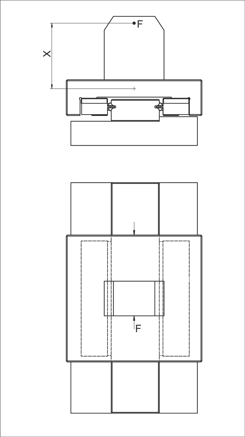
Example 1: Equivalent Load P per Roller
Assumptions:
- Linear guides type R 6
- AC 6 cage with 8 rollers (RA = 8)
- Load F = 350 N
- Lever arm distance X = 120 mm
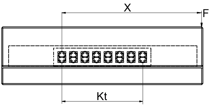
For AC 6 type roller cage, the following applies:
Step 1: Calculate load-bearing length Kt
Step 2: Determine correction factor
Rtmin = 1 roller (according to chapter 5.1 AC 6 cage technical specifications)
C = 530 N (max. permissible load capacity per roller)
Step 3: Calculate equivalent load P per roller
✓ P (334 N) is less than C (530 N), therefore this design is correct.
Example 2: Equivalent Load P per Roller (20 Rollers)
Assumptions:
- Linear guides type R 6
- AC 6 cage with 20 rollers (RA = 20)
- Load F = 6,500 N (acting vertically on dual guideway system)
- C = 530 N (max. permissible load capacity per roller)
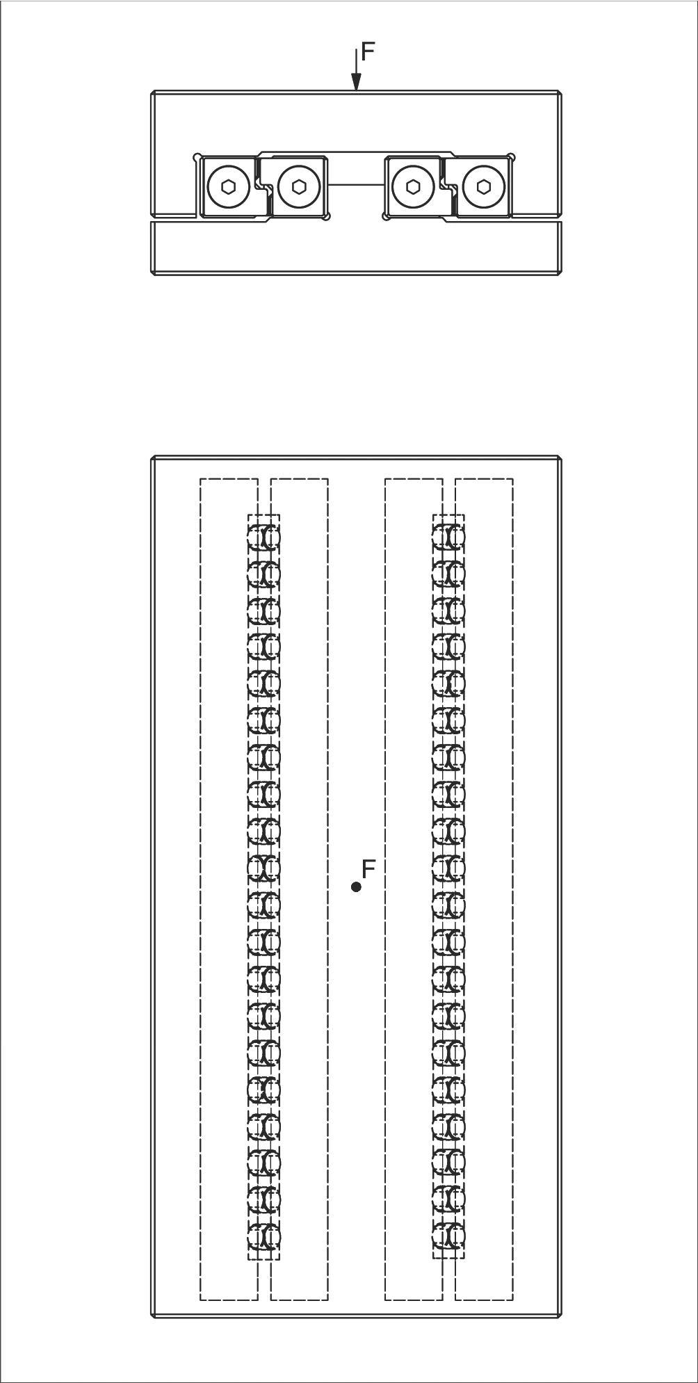
Calculation Steps:
Step 1: Calculate number of load-bearing rollers
Since the load acts vertically, each guideway in the dual system bears half the load.
Step 2: Calculate equivalent load P per roller
✓ P (325 N) is less than C (530 N), therefore this design is correct. Safety factor = 530 / 325 ≈ 1.63
Example 3: Equivalent Load P per Ball
Assumptions:
- Rigid cage structure
- Linear guides type R 6
- AK 6 cage with 12 balls (RA = 12)
- Cage division t = 9 mm
- Load F = 240 N
- Lever arm distance X = 75 mm
- C = 65 N (max. permissible load capacity per ball)

Calculation Steps:
Step 1: Calculate load-bearing length Kt
Step 2: Determine correction factor Rtmin
According to the Rtmin calculation chart in chapter 12.3:
- Structure type: Rigid structure (A)
- X/Kt = 75/99 = 0.76 (less than 1)
- From chart: Rtmin ≈ Rt/2
Step 3: Calculate equivalent load P per ball
✓ P (30.3 N) is less than C (65 N), therefore this design is correct. Safety factor = 65 / 30.3 ≈ 2.15
Example 4: Equivalent Load P for RNG Guideways
Assumptions:
- RNG type linear guideway
- KBN cage with 10 rollers (RA = 10)
- Load F = 15,000 N
- Lever arm distance X = 50 mm
- Linear guideway center distance Q = 100 mm

Calculation Steps:
Step 1: Calculate number of load-bearing rollers RT
Step 2: Calculate equivalent load P₁ from eccentric load
Step 3: Calculate equivalent load P₂ from vertical load
Step 4: Calculate total equivalent load P
Step 5: Select appropriate KBN cage size
- KBN 4: C = 850 N < 3,000 N ✗
- KBN 6: C = 1,800 N < 3,000 N ✗
- KBN 9: C = 3,900 N > 3,000 N ✓
✓ Select KBN 9 cage, C = 3,900 N > P = 3,000 N. Safety factor = 3,900 / 3,000 ≈ 1.30
KBN Cage Dimensions and Load Capacity
| Type | Size | Roller Diameter Dw (mm) | Division t (mm) | Width w (mm) | Load Capacity C per Roller (N) |
|---|---|---|---|---|---|
| KBN | 4 | 4.5 | 6.5 | approx. 4 | 850 |
| 6 | 6.5 | 8.5 | approx. 5 | 1,800 | |
| 9 | 9 | 12 | approx. 7.5 | 3,900 | |
| 12 | 12 | 15 | approx. 9 | 6,500 |
Example 5: Equivalent Load P per Needle
Assumptions:
- Linear guideway type N/O 2025
- SHW 15 cage with length K = 194 mm
- Cage end width w = 2.9 mm
- Needle division t = 4 mm
- Load F = 5,000 N
- Lever arm distance X = 280 mm
- Guideway center distance Q = 75 mm
- C = 750 N (max. permissible load capacity per needle)
Calculation Steps:
Step 1: Calculate total number of needles RA
Step 2: Calculate number of load-bearing needles Rt
Step 3: Calculate equivalent load P per needle
✓ P (388.3 N) is less than C (750 N), therefore this design is correct. Safety factor = 750 / 388.3 ≈ 1.93
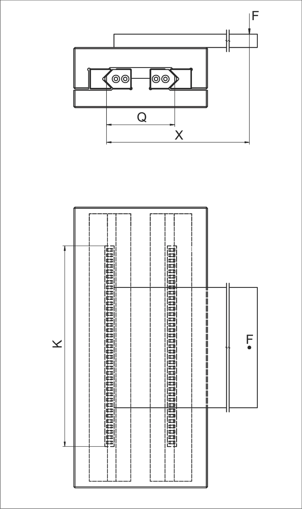
Example 6: Equivalent Load P per Roller (Longitudinal and Lateral)
Assumptions:
- Rigid structure
- Linear guides type R 12
- Cage type AC 12, length K = 400 mm
- F = 2,000 N
- X = 500 mm
- X1 = 200 mm
- Q = 100 mm
- C = 2,500 N (see chapter 5.1 AC 12 cage technical specifications)
For the roller cage AC 12 the following applies:
Calculate load-bearing length Kt
Calculate total number of rollers RA
Calculate number of load-bearing rollers Rt
Calculation for P per roller:
Load laterally
Load longitudinally
Total equivalent load
✓ P is smaller than C. The design is correct.
Example 7: Equivalent Load P for Recirculating Unit
Assumptions:
- Recirculating unit type SR 6-100
- Linear guideway type R 6
- Number of recirculating units Rt = 2 (dual configuration)
- Load F = 6,000 N
- C = 2,150 N (max. permissible load capacity per recirculating unit)

Calculation Steps:
Step 1: Calculate single-side load
Step 2: Calculate equivalent load P per recirculating unit
✓ P (1,500 N) is less than C (2,150 N), therefore this design is correct. Safety factor = 2,150 / 1,500 ≈ 1.43
Example 8: Moment Load M Longitudinally and Laterally
Assumptions:
- Recirculating unit type SR 6-150
- Linear guideway type RD 6
- Load F = 2,000 N
- Lever arm distance X = 45 mm
- ML = 112 Nm (permissible moment load longitudinally and laterally)
Calculation Steps:
Step 1: Convert lever arm distance to meters
Step 2: Calculate actual moment load M
Step 3: Verify moment load is within permissible range
- Actual moment load: M = 90 Nm
- Permissible moment load: ML = 112 Nm
- M < ML ✓
✓ Moment load M (90 Nm) is less than permissible load ML (112 Nm), therefore this design is correct. Safety factor = 112 / 90 ≈ 1.24
Example 9: Equivalent Loads PL and PQ
Assumptions:
- Recirculating unit type NRT 26 111 (top)
- Recirculating unit type NRT 19 077 (bottom and side)
- C = 98,000 N (top recirculating unit)
- C = 43,000 N (bottom and side recirculating units)
- K = 700 mm
- Kt = 450 mm
- Rtmin = 0.5
- F = 83,000 N
- X = 500 mm
- Y = 100 mm

Calculation Steps:
Load longitudinally
Load laterally