Design Overview
The diagrams and tables below describe the design of the adjacent construction. Please pay particular attention to the connection areas, as any deviation will affect the overall accuracy and rigidity of the roller bearing.
To avoid degradation of bearing friction torque, accuracy requirements, and operating characteristics, the recommended tolerances must not be exceeded.
Important Note
The bore and outer diameter of myonic AXCR bearings are manufactured to the P5 / DIN 620 standard with tight tolerance limits. This enables precise fits, so the accuracy of the bearing can be transferred to the table.
Fit Type Description
Press Fit (Interference Fit)
In principle, when the fit is too tight, the radial preload of the bearing increases. As a result:
The Following Increase
- Surface pressure in the raceway
- Bearing friction
- Bearing heat generation
- Amount of wear
The Following Decrease
- Maximum speed
- Service life
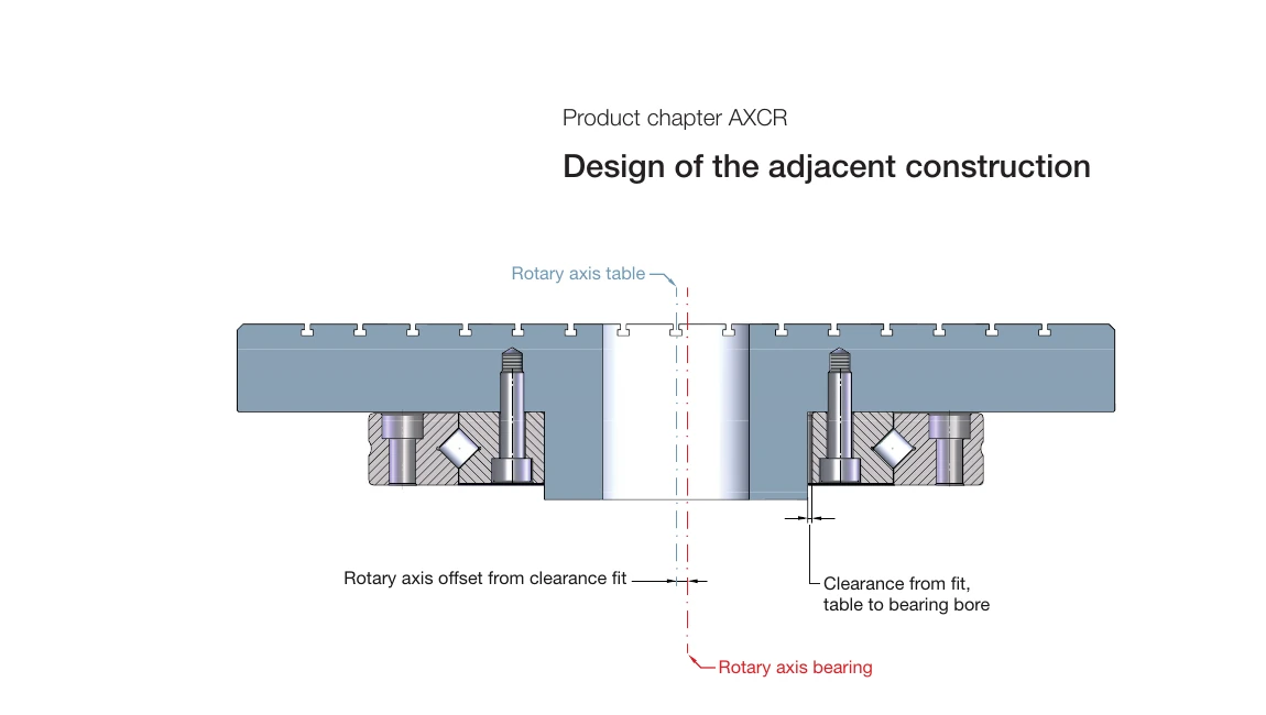
Clearance Fit
If the rotating ring is not supported in a clearance fit, the raceway of the rotating shaft may shift relative to the table center. The clearance from the mating table to the bearing bore (and likewise the clearance from the bearing outer diameter to the table when the outer ring rotates) may increase the radial runout.
Applications with Lower Accuracy Requirements
In applications with lower accuracy requirements, the ring can also be fastened with screws in a clearance fit. The wall thickness of the table adapter at the bearing bore (or outer diameter) must be large enough to exclude the risk of uncertain operating conditions such as vibration, radial runout errors, and impaired repeatability.
Centered Shafts / Tables
Centred Shafts / Tables
Centering can be performed by means of a shaft clearance fit to the rotating shaft. Due to its solid rings, the AXCR bearing is less sensitive to a non-positively locked shaft than the AXRY bearing. However, reduced shaft rigidity and the possible risk of radial runout problems or displacement of the rotating shaft under overload must be accepted.
Note on Radial Runout Measurement
A radial runout measurement performed with a centered table and a fitted measuring ball does not correspond to the catalog values below. In such a precisely centered measurement, only the radial runout of the raceway and the form error of the measuring setup are recorded. If the measuring setup is executed precisely, the measured values will be lower than the specified myonic radial runout values. The myonic radial runout values include the radial runout error of the raceway and the roundness of the bore.
Fastening Possibilities
Fastening Possibilities AXCR-U / AXCR-S
myonic offers the following fastening methods in the standard series:
SA = Grooves Opposite
Two cases must be considered for the connection dimensions. For fastening method SA, because the two rings are offset from each other, no collision with the adjacent construction occurs, so there are no specific connection dimension requirements.
SS = Grooves Identical
For fastening method SS, there is no offset between the inner and outer rings, so the specified table values apply. The diameter value da is the maximum value, and the diameter value Di is the minimum value.
Special Feature
Both standard designs contain exactly the same individual rings. Depending on the required fastening method, only one inner ring is installed in a mirrored arrangement.
The individual rings are always unsupported on the cylindrical counterbore side, which means that no collision occurs in fastening method "SA".
On the other hand, if the ring arrangement "SS" is selected, a lower overall height results because the two recessed cylindrical counterbores are located on the same side.
Precision Manufacturing of Offset "V"
The offset "V" shown in detail "X" can be manufactured to a tolerance of a few micrometers according to customer requirements. This eliminates the need for complex shim rings and costly assembly.
Recommended Connection Dimensions
Recommended Connection Dimensions (applicable for fastening method SS)

The following connection dimensions apply to fastening method SS (Grooves Identical):
| Cross Roller Bearing | Connection Dimension Ø da MAX [mm] | Connection Dimension Ø Di MIN [mm] |
|---|---|---|
| AXCR 80-U | 122.0 | 130.0 |
| AXCR 90-U | 144.5 | 152.5 |
| AXCR 115-U | 173.0 | 181.0 |
| AXCR 160-U | 223.0 | 231.0 |
| AXCR 210-U | 295.0 | 303.0 |
| AXCR 270-U | 331.0 | 339.0 |
| AXCR 350-U | 439.0 | 447.0 |
| AXCR 360-U | 450.0 | 458.0 |
| AXCR 540-U | 626.0 | 634.0 |
| AXCR 130-S | 162.0 | 170.0 |
| AXCR 150-S | 184.5 | 192.5 |
| AXCR 180-S | 213.0 | 221.0 |
| AXCR 220-S | 253.0 | 261.0 |
| AXCR 280-S | 315.0 | 323.0 |
| AXCR 360-S | 394.5 | 402.5 |
Dimension Symbol Legend
- da MAX - Maximum shaft diameter (safe distance to inner ring groove)
- Di MIN - Minimum housing bore diameter (safe distance to outer ring groove)
Recommended Minimum Wall Thicknesses
Recommended Minimum Wall Thicknesses

To ensure that the housing does not deform due to bearing installation or load, a sufficient wall thickness must be guaranteed. The recommended minimum wall thicknesses and maximum through-hole diameters for each model are listed below:
AXCR-U Series
| Cross Roller Bearing | Minimum Wall Thickness [mm] | Maximum Through-hole Ø [mm] |
|---|---|---|
| AXCR 80-U | 15 | 50 |
| AXCR 90-U | 21 | 48 |
| AXCR 115-U | 22 | 71 |
| AXCR 160-U | 24 | 113 |
| AXCR 210-U | 30 | 150 |
| AXCR 270-U | 23 | 224 |
| AXCR 350-U | 34 | 283 |
| AXCR 360-U | 32 | 297 |
| AXCR 540-U | 31 | 478 |
AXCR-S Series
| Cross Roller Bearing | Minimum Wall Thickness [mm] | Maximum Through-hole Ø [mm] |
|---|---|---|
| AXCR 130-S | 13 | 104 |
| AXCR 150-S | 13 | 124 |
| AXCR 180-S | 13 | 154 |
| AXCR 220-S | 13 | 194 |
| AXCR 280-S | 13 | 254 |
| AXCR 360-S | 13 | 334 |
Design Principles
Wall Thickness Design
Ensure sufficient housing wall thickness to prevent deformation during installation and operation.
Rigidity Design
The adjacent construction should have sufficient rigidity to withstand the loads transferred by the bearing.
Heat Dissipation Consideration
The design should allow the heat generated by the bearing to be dissipated effectively.
Seal Protection
Consider adding additional sealing or dust protection measures.
Mounting Hole Design
The mounting holes on the bearing rings should match the mounting holes of the adjacent construction.
Mounting Hole Notes
- Mounting hole positions should align with the hole positions on the bearing rings
- Screw specifications should meet the recommended torque requirements
- Use the correct screw torque and avoid over-tightening
- Tighten all screws evenly; a diagonal sequence is recommended
Recommended Screw Torque
Screw torque according to DIN 912, strength class 10.9. For detailed torque values, please refer to the product dimension tables.
Design Recommendations
Best Practices
- An undersized or imprecise adjacent construction significantly reduces the rigidity at the bearing location
- Conversely, structural support through additional components can also increase rigidity
- Consult our application engineering team at sales@eb-system.com during the design phase
- Use FEA (Finite Element Analysis) to verify structural rigidity
- Consider the effect of temperature changes on the fits
- Reserve sufficient space for maintenance and inspection