Fastening Methods
myonic offers the following fastening methods for AXCR-U / AXCR-S in the standard series:

Standard Fastening Designs
| Code | Design Name | Description |
|---|---|---|
| SA | Grooves Opposite | The fastening grooves of the inner and outer rings are on opposite sides. The ring is never supported on the cylindrical counterbore side, so "SA" eliminates the possibility of screw collision. |
| SS | Grooves Identical | The fastening grooves of the inner and outer rings are on the same side. Since the countersunk holes face the same direction, the overall height is lower. |
Note
More detailed information can be found in the "Adjacent Construction Design" section.
Ring Design System
The designation system for ring designs is as follows (available upon request):
| Code | Design Type | Description |
|---|---|---|
| S | Countersunk Hole | Countersunk hole - mounting hole with countersink |
| N | No Holes | No holes - no mounting holes on the ring |
| G | Threaded Bore | Threaded bore - mounting hole with internal thread |
| B | Through Bore | Through bore - smooth through mounting hole |
Designation Order
Designation order: First position = outer ring design, Second position = inner ring design
Example: SN = outer ring with countersunk hole, inner ring with no holes
Ring Design Combinations
The following are common ring design combinations (designation order: first position = outer ring design, second position = inner ring design):
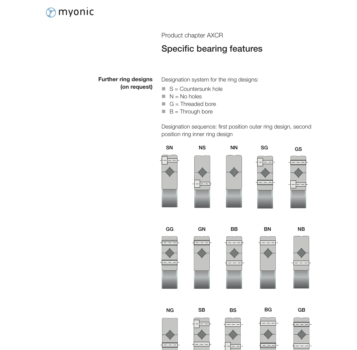
Example: SG
- First position S: Outer ring design is countersunk hole
- Second position G: Inner ring design is threaded bore
Seals
myonic cross roller bearings are equipped as standard with non-ground gap seals or labyrinth seals.

Gap Seal Features
- Formed by a gap, it effectively prevents the penetration of dust particles
- Does not cause additional friction (temperature)
- Suitable for most standard applications
For special applications, ground seals made from various different materials can be used.
Accuracy
myonic production is performed on the same production system as all other ultra-precision bearings. This way, myonic AXCR cross roller bearings can achieve similar accuracy to AXRY or AXDR bearings.
The measuring accuracy P5 for the bore and the outer diameter allows for the manufacture of high-precision fits and thus the accurate guidance of rotary axes.
Accuracy Grades
| Accuracy Parameter | Description | Grade |
|---|---|---|
| Axial Runout | Axial runout | P4, P2, UP optional |
| Radial Runout | Radial runout | P4, P2, UP optional |
The axial and radial runout accuracy of AXCR-U and AXCR-M corresponds to grades P4, P2 and UP. With AXCR-S, you can choose between standard and restricted runout accuracy (PRR50).
More Information
For detailed accuracy information, please refer to the product tables.
Lubrication
AXCR bearings can be lubricated with grease or oil. The standard configuration is grease lubrication.
| Lubrication Type | Description | Application |
|---|---|---|
| Grease Lubrication | Standard configuration, lifetime lubrication | Most standard applications |
| Oil Lubrication | Supplied ungreased, requires external oil supply (order code L120) | Available on request |
Preload
myonic cross roller bearings are available in bearing clearance, light preload and standard preload versions.
| Preload Type | Characteristics | Application |
|---|---|---|
| Bearing Clearance | Clearance between rollers and raceways | Special application requirements |
| Light Preload | Lower friction torque | Applications requiring lower friction |
| Standard Preload | Higher rigidity with increased friction torque | Most standard applications |
With higher preload, rigidity increases; at the same time, the bearing friction torque also increases. Generally, most AXCR bearings are assembled with standard preload.
Customer-specific Designs (J-numbers)
myonic produces customer-specific bearing designs, designated with J and a number.
Such J-numbers can include the following:
- Application-specific preload values or friction torques
- Special instructions for marking or packaging
- Special lubrication systems
- Modified tolerances
Note
J-numbers are assigned by myonic. For customized designs, email sales@eb-system.com.
Preservatives
The corrosion protection oil used is compatible with most greases and oils produced on a mineral oil basis.
When using synthetic lubricants and thickeners other than lithium (complex) soaps, please check compatibility. In case of incompatibility, email sales@eb-system.com to clarify the further procedure.
Standard Series: myonic cross roller bearings in the standard series do not receive surface treatment.
Surface Treatment
myonic cross roller bearings in the standard series do not receive surface treatment.
In case of incompatibility, email sales@eb-system.com to clarify the further procedure.
Limiting Speeds / Temperatures / Friction
The limiting speeds stated in the dimension tables can be reached in short-term or long-term continuous operation of the selected cross roller bearing.
Operating Condition Notes
- During long-term operation in the range close to the limiting speed, bearings gradually "heat up"
- Higher preload leads to higher rigidity together with higher friction
- The friction torque of cross roller bearings is mainly influenced by the selected preload
Relubrication
The selected lubricant, particularly its viscosity and filling quantity, has a direct influence on friction. Standard pre-lubricated bearings are suitable for medium-speed operation and shorter continuous operation up to the limiting speed.
Metering systems are most suitable for relubrication purposes. In the case of manual relubrication, there is a risk of over-lubrication.
Warning
During break-in or relubrication, an appropriate break-in running time is advisable, and direct high-speed operation should be avoided.
Calculation of Rigidity
Rigidity calculations are performed under the following parameters:
- Applied radial and axial loads as well as fitting moments
- Light preload
- Normal adjacent construction and screw connections (according to the information in the myonic catalog)
In all product groups, the same FEM calculation procedure with precisely defined parameters is used. The rigidity values stated in the product tables are directly comparable (e.g., AXRY vs. AXDR vs. AXCR).
Adjacent Construction Influence
An undersized, imprecise adjacent construction substantially reduces the rigidity at the bearing position; on the other hand, rigidity can be increased through supported, continuous adjacent construction.
For detailed information, please refer to the "Machine Tool Bearing General Technology" section.
Next Steps
Learn more about AXCR bearing technical information:
- Limiting Load Diagrams - Static limiting load diagrams for each size series
- Recommended Shaft Fits - Shaft fit tolerance selection guide
- Recommended Housing Fits - Housing fit tolerance selection guide