Dimension Markings
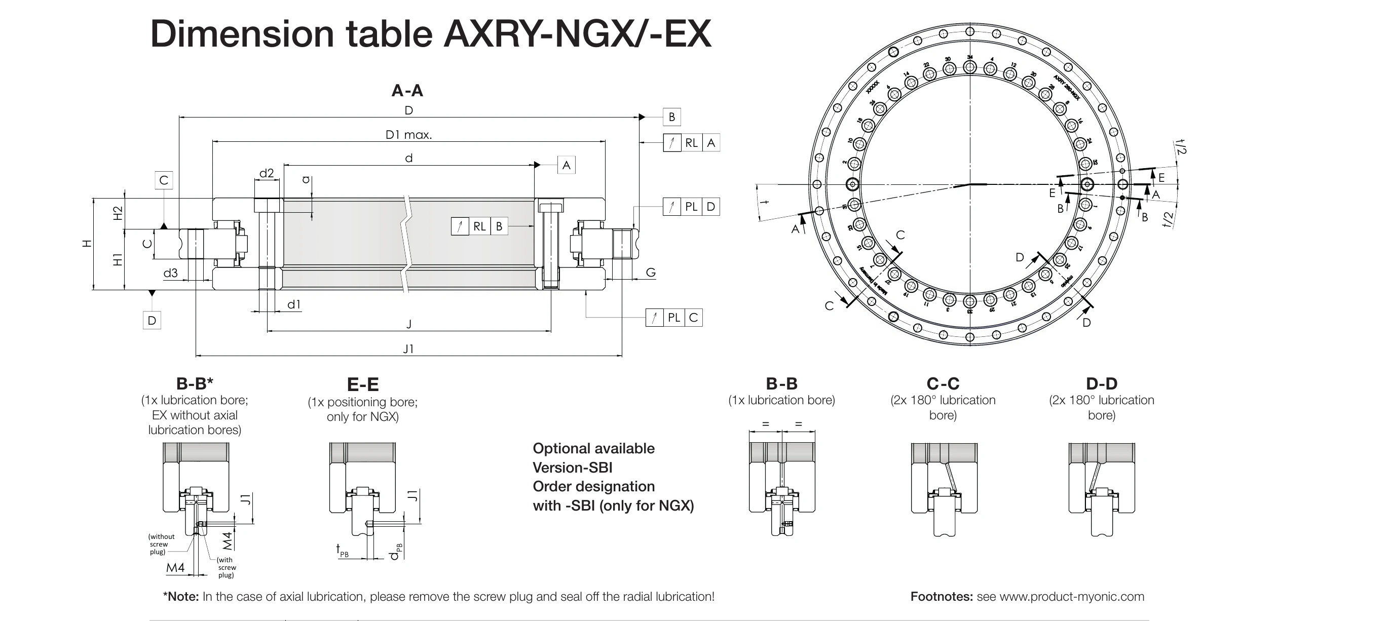
*For axial lubrication, remove the screw plug and close the radial lubrication bore. Source: myonic official catalogue EMO 2025.
(Click the image to enlarge)
1) Including fastening screws or extraction thread.
2) Tightening torque for screws acc. DIN 912, strength class 10.9.
3) Attention! For fixing holes in the adjacent construction, observe the pitch of the bearing bores.
4) Screw counterbores in large L-ring open to bearing bore. Bearing inside diameter is not supported in this area.
5) Please enquire in case of high speed applications.
6) Result after in-house assembly: measuring speed nconst = 5 min-1; with myonic standard grease and standard amount; without supporting ring; bearing frictional torque can increase by a factor of 2.5 towards the limiting speed value.
Main Dimensions
- d: Bore diameter (shaft diameter) [mm]
- D: Outside diameter (housing bore diameter) [mm]
- H: Total height [mm]
- H1: Table side height [mm]
- H2: Shaft side height [mm]
- Weight: [kg]
| Model | d [mm] | D [mm] | H [mm] | H1 [mm] | H2 [mm] | Weight [kg] |
|---|---|---|---|---|---|---|
| AXRY 180-NGX | 180 | 280 | 43 | 29 | 14 | 7.1 |
| AXRY 200-NGX | 200 | 300 | 45 | 30 | 15 | 9.1 |
| AXRY 260-NGX | 260 | 385 | 55 | 36.5 | 18.5 | 17.5 |
| AXRY 325-NGX | 325 | 450 | 60 | 40 | 20 | 24.5 |
| AXRY 395-NGX | 395 | 525 | 65 | 42.5 | 22.5 | 32.2 |
| AXRY 460-NGX | 460 | 600 | 70 | 46 | 24 | 44.8 |
| AXRY 580-NGX | 580 | 750 | 90 | 60 | 30 | 86.0 |
| AXRY 650-NGX | 650 | 870 | 122 | 78 | 44 | 165.2 |
Load Capacity and Performance Data
- Ca: Dynamic axial load rating [kN]
- C0a: Static axial load rating [kN]
- Cr: Dynamic radial load rating [kN]
- C0r: Static radial load rating [kN]
- Ckl: Tilting rigidity [kNm/mrad]
- nG: Limiting speed [min-1]
- MR: Bearing frictional torque [Nm] (measured after in-house assembly, nconst = 5 min-1)
| Model | Ca [kN] | C0a [kN] | Cr [kN] | C0r [kN] | Ckl [kNm/mrad] | nG [min-1] | MR [Nm] |
|---|---|---|---|---|---|---|---|
| AXRY 180-NGX | 139.3 | 755.0 | 99.4 | 200.3 | 51.1 | 600 | 5 |
| AXRY 200-NGX | 151.0 | 871.2 | 122.1 | 273.9 | 62.6 | 450 | 6 |
| AXRY 260-NGX | 220.1 | 1520.6 | 138.3 | 349.0 | 153.5 | 300 | 9 |
| AXRY 325-NGX | 249.3 | 1900.8 | 181.7 | 531.4 | 272.1 | 200 | 13 |
| AXRY 395-NGX | 275.7 | 2281.0 | 199.2 | 633.8 | 459.4 | 175 | 19 |
| AXRY 460-NGX | 299.5 | 2661.1 | 232.5 | 739.0 | 736.9 | 150 | 25 |
| AXRY 580-NGX | 584.6 | 4457.4 | 284.5 | 867.2 | 1207.0 | 80 | 60 |
| AXRY 650-NGX | 1010.7 | 7682.4 | 459.6 | 1317.1 | 1880.1 | 70 | 70 |
Runout Accuracy
- PL: Axial runout (Plan Lauf) [μm]
- RL: Radial runout (Radial Lauf) [μm]
- Standard: Standard accuracy (no suffix)
- Restricted (PRR50): Restricted accuracy (ordering code -PRR50)
- High accuracy (PRR30): High accuracy (ordering code -PRR30)
| Model | Standard PL & RL [μm] | Restricted (PRR50) PL & RL [μm] | High accuracy (PRR30) PL & RL [μm] |
|---|---|---|---|
| AXRY 180-NGX | 4 | 2 | - |
| AXRY 200-NGX | 4 | 2 | - |
| AXRY 260-NGX | 6 | 3 | 2 |
| AXRY 325-NGX | 6 | 3 | 2 |
| AXRY 395-NGX | 6 | 3 | 2 |
| AXRY 460-NGX | 6 | 3 | 2 |
| AXRY 580-NGX | 10 | 5 | 3 |
| AXRY 650-NGX | 10 | 5 | 3 |
Height Tolerances
- H1 tolerance: Table side height tolerance (connection dimension tolerance) [mm]
- H2 tolerance: Shaft side height tolerance [mm]
| Model | H1 tolerance [mm] | H2 tolerance [mm] |
|---|---|---|
| AXRY 180-NGX | +0.03 / -0.03 | +0.025 / -0.025 |
| AXRY 200-NGX | +0.03 / -0.03 | +0.025 / -0.025 |
| AXRY 260-NGX | +0.04 / -0.04 | +0.025 / -0.025 |
| AXRY 325-NGX | +0.05 / -0.05 | +0.025 / -0.025 |
| AXRY 395-NGX | +0.05 / -0.05 | +0.025 / -0.025 |
| AXRY 460-NGX | +0.06 / -0.06 | +0.03 / -0.03 |
| AXRY 580-NGX | +0.25 / -0.25 | +0.25 / -0.25 |
| AXRY 650-NGX | +0.25 / -0.25 | +0.25 / -0.25 |
Fixing Hole Specifications
- d1: Through-hole diameter of fixing holes (inner ring) [mm]
- d2: Counterbore diameter of fixing holes (inner ring) [mm]
- a: Counterbore depth of fixing holes (inner ring) [mm]
- d3: Diameter of fixing holes (outer ring) [mm]
- Extraction thread: Size / quantity
- MA: Screw tightening torque [Nm] (acc. DIN 912, strength class 10.9)
- dPB: Positioning bore diameter [mm]
- tPB: Positioning bore depth [mm]
| Model | Inner Ring Fixing Holes | Outer Ring Fixing Holes | Extraction Thread Size / Qty | Screw Torque MA [Nm] | Positioning Bore | |||||
|---|---|---|---|---|---|---|---|---|---|---|
| d1 [mm] | d2 [mm] | a [mm] | Qty | d3 [mm] | Qty | dPB [mm] | tPB [mm] | |||
| AXRY 180-NGX | 7 | 11 | 6.4 | 46 | 7 | 45 | M8 / 3 | 14 | 5 | 5 |
| AXRY 200-NGX | 7 | 11 | 6.4 | 46 | 7 | 45 | M8 / 3 | 14 | 5 | 5 |
| AXRY 260-NGX | 9.3 | 15 | 8.6 | 34 | 9.3 | 33 | M12 / 3 | 34 | 5 | 5 |
| AXRY 325-NGX | 9.3 | 15 | 8.6 | 34 | 9.3 | 33 | M12 / 3 | 34 | 5 | 5 |
| AXRY 395-NGX | 9.3 | 15 | 8.6 | 46 | 9.3 | 45 | M12 / 3 | 34 | 5 | 5 |
| AXRY 460-NGX | 9.3 | 15 | 8.6 | 46 | 9.3 | 45 | M12 / 3 | 34 | 5 | 5 |
| AXRY 580-NGX | 11.4 | 18 | 10.6 | 46 | 11.4 | 42 | M12 / 6 | 68 | 8 | 8 |
| AXRY 650-NGX | 14 | 20 | 12.6 | 46 | 14 | 42 | M12 / 6 | 116 | 10 | 10 |
Lubrication Hole Configuration
Standard Configuration (NGX - Inner Ring Rotates)
B-B
1x lubrication bore
(for axial lubrication, remove the plug and close the radial bore)
E-E
1x positioning bore
(positioning bore)
Optional Configuration (SBI - Outer Ring Rotates) - Ordering Code -SBI
B-B
1x lubrication bore
C-C
2x lubrication bores at 180°
D-D
2x lubrication bores at 180°
Note (B-B Configuration)
For axial lubrication, remove the screw plug and close the radial lubrication bore!
CAD Model Download
EB-System Download Center
CAD models (STEP) and data sheets can be downloaded from the EB-System Download Center: