5.2.1 Carriages and Guide Rails
When designing SCHNEEBERGER MONORAIL BZ guide rails with rack drives, the following should be noted:
Load Capacity
Guide rails with carriages do not differ in design from standard guide rails. The load capacity of MONORAIL BM conforms to the SCHNEEBERGER MONORAIL and AMS product catalog.
For MONORAIL BZ, however, it should be noted that the total load capacity of the system is limited compared to MONORAIL BM. The reason for this is the high load on the lateral screw connection due to the lever action of the guide rail under lateral force, the friction locking of the internal screw connection between the guide rail and rack, and the extremely small contact area with the rack. The values in the table below based on strength class 12.9 screw connections apply to permissible lateral loads ± FY as well as permissible tensile and compressive forces ± FZ. These values apply per carriage.
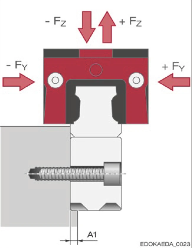
Effect of tensile, compressive, and lateral forces
Maximum Tensile, Compressive, and Lateral Forces (N)
| Size/Carriage Type | +FY (N) | -FY (N) | +FZ (N) | -FZ (N) |
|---|---|---|---|---|
| BZ 25 A/C/E | 5275 | 1840 | 3060 | 8651 |
| B/D | 6375 | 2200 | 3060 | 10455 |
| BZ 35 A/C/E | 9675 | 3600 | 5580 | 24381 |
| B/D | 11675 | 4290 | 5580 | 29421 |
Service Life
For worktable systems with rack drives, additional forces perpendicular to the direction of motion are generated at the gear mesh. These forces are transmitted through the pinion, motor, and carriage to the guide rail and must be taken into account when calculating service life.
Due to the helical gears, when driving transverse to the longitudinal axis of the guide rail, a force Fy is generated, where Fy = 0.35 • Fx. The value 0.35 comes from the helix angle of the gear β = 19°31'42". This force remains constant when the drive force is constant. Its direction reverses with the direction of acceleration (when changing from acceleration to braking).
Additionally, a force Fz perpendicular to the rack is generated, directed away from the rack, where Fz = 0.36 • Fx, due to the pressure angle of the tooth surface being approximately 20°. This force fluctuates. As a guideline for service life calculation, Fz ≈ 2/3 Fz_max should be used.
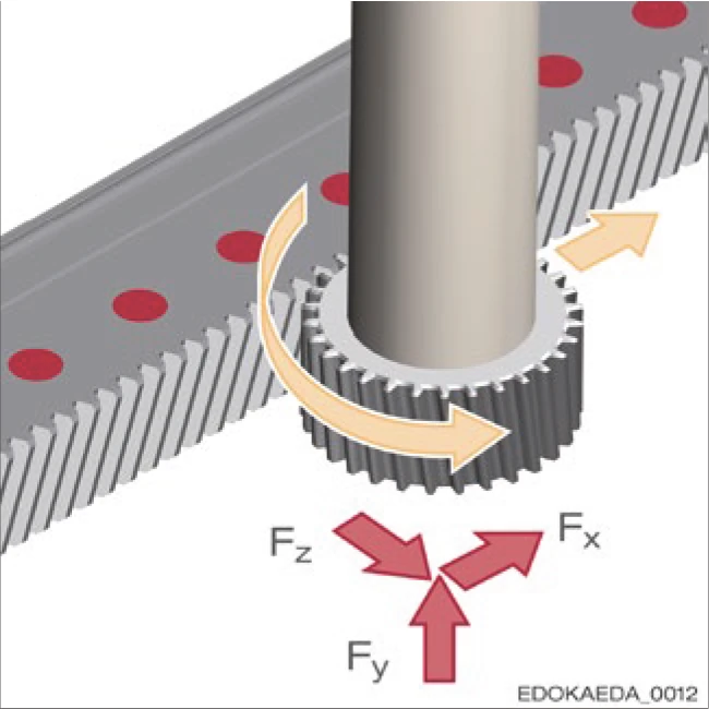
Forces on the rack
Fy: Force in y-direction Fz: Force in z-direction
Forces When Using E-Type Carriages
When using E-type carriages, attention should be paid to the type and direction of forces. Due to the lateral connection of the carriage during axial sliding, torques may be generated, which can lead to internal additional forces that may significantly reduce service life.
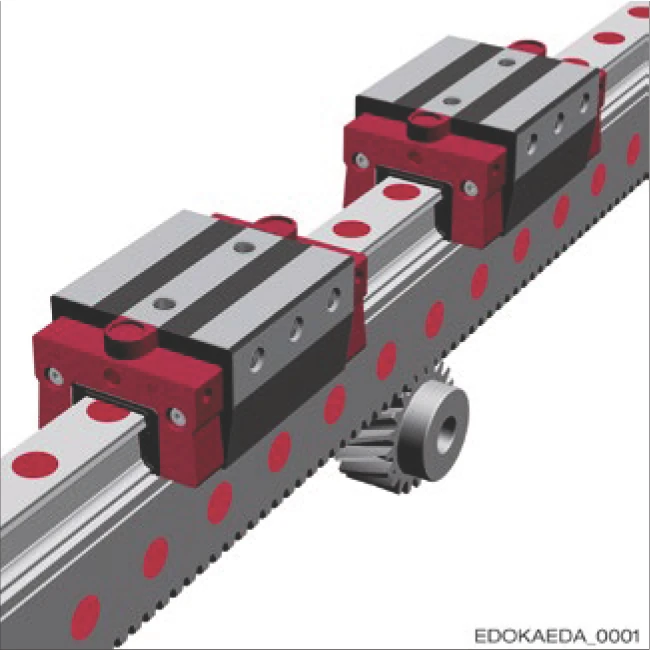
Rack drive with two E-type carriages
5.2.2 Racks
The calculation principles listed below are used for rough estimation of possible loads and service life of rack drives. However, for precise design, detailed calculations are required, which can be requested from SCHNEEBERGER as needed.
Load on Rack and Pinion

Rack with longitudinal force FL and pinion with torque TN
The table below provides an overview of maximum force FL and maximum torque TN, depending on the size and rack design of MONORAIL BZ, the number of teeth z of the pinion, and the number of load changes.
The specified values are valid under conditions of effective lubrication, smooth operation, and stable bearings.
Safety factors for tooth root stress SF ≥ 1.4 and tooth surface stress SH ≥ 1.0 have been included in the formula.
Based on experience, a safety factor SB ≈ 1.0 - 4.0 for operating conditions (angular errors, insufficient lubrication, dirt, etc.) needs to be considered.
Depending on the application, we recommend using values for 10⁶ or 10⁷ load changes. The value 10⁵ is only used in special cases, such as static loads, in consultation with SCHNEEBERGER.
The applied number of load changes is determined as follows:
If the number of teeth in the primarily used rack segment exceeds ten times the number of pinion teeth z, it can be designed for 10⁶, otherwise 10⁷ load changes should be assumed.
| Rack Type and Design | Pinion Teeth z | 10⁵ | 10⁶ | 10⁷ | |||
|---|---|---|---|---|---|---|---|
| TN (Nm) | FL (N) | TN (Nm) | FL (N) | TN (Nm) | FL (N) | ||
| BZ 25 | |||||||
| Soft | 20 | 104 | 4895 | 34.2 | 1610 | 17.5 | 827 |
| Hardened | 20 | 138 | 6500 | 132 | 6240 | 102 | 4800 |
| Soft | 40 | 295 | 6900 | 132 | 3120 | 70 | 1600 |
| Hardened | 40 | 281 | 6600 | 242 | 5700 | 181 | 4280 |
| BZ 35 | |||||||
| Soft | 20 | 217 | 8180 | 73 | 2750 | 34 | 1280 |
| Hardened | 20 | 285 | 10700 | 273 | 10300 | 214 | 8000 |
| Soft | 42 | 627 | 11200 | 292 | 5240 | 183 | 3290 |
| Hardened | 42 | 603 | 10800 | 522 | 9300 | 397 | 7130 |
Force and Torque Calculations
Vertical Stroke Axis
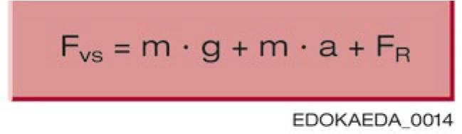
Fvs = Thrust force (N)
m = Moving mass (kg)
g = Gravitational acceleration = 9.81 m/s²
a = Acceleration (m/s²)
FR = Friction resistance (N)
Horizontal Stroke Axis

Fvs = Thrust force (N)
m = Moving mass (kg)
a = Acceleration (m/s²)
FR = Friction resistance (N)
Acceleration

a = Acceleration (m/s²)
v = Velocity (m/s)
tb = Acceleration time (s)
Friction Resistance

FR = Friction resistance (N)
µ = Friction coefficient
m = Moving mass (kg)
g = Gravitational acceleration = 9.81 m/s²
Required Torque

Merf = Required torque
Fvs = Thrust force (N)
d = Reference diameter (mm)
Permissible Torque

Mzul = Permissible torque
TN = Torque (from table above)
SB = Operating condition safety factor
Based on experience, a safety factor (SB ≈ 1.0 – 4.0) for operating conditions (angular errors, insufficient lubrication, dirt, etc.) should be considered.
The following condition must be met:

Mzul = Permissible torque
Merf = Required torque