Correct installation is critical for the performance of SCHNEEBERGER MONORAIL guideway systems. This chapter details the lateral locating surface specifications, guide rail orientation methods, installation method selection, and support surface accuracy requirements.
4.12.1 Lateral Locating Surfaces for Guide Rails and Carriages
To simplify the installation of SCHNEEBERGER MONORAIL guideway systems and achieve precise alignment of guide rails and carriages, the locating surfaces of guide rails and carriages should be matched with lateral locating surfaces. This allows higher lateral forces to be transmitted. Please refer to Section 4.9 "Guide Rail Mounting" and Section 4.11 "Carriage Fastening" for the permissible lateral forces without locating surfaces.
Observing the following locating surface height specifications ensures safe force absorption and sufficient clearance for the carriage. The carriages and guide rails have chamfers at the locating surface edges, which means the connecting structure can be designed without relief grooves. The specified fillet radii are maximum values that ensure proper seating of carriages and guide rails against the locating surfaces.

Connecting Structure Dimensions
Dimension Symbol Description:
- r1: Maximum fillet radius for lateral locating surface
- r2: Maximum fillet radius for front locating surface
- H1: Locating surface height range
- H2: Minimum locating surface height
Lateral Locating Surface Dimension Specifications
| Type | Size | H1, min | H1, max | H2, min | r1, max | r2, max |
|---|---|---|---|---|---|---|
| MR | 25 | 3.5 | 6 | 5 | 0.8 | 0.8 |
| 35 | 4.5 | 7.5 | 6 | 0.8 | 0.8 | |
| 45 | 6 | 9.5 | 8 | 0.8 | 0.8 | |
| 55 | 7.5 | 12.5 | 10 | 1.3 | 1.3 | |
| 65 | 9.5 | 13.2 | 12 | 1.8 | 0.8 | |
| 100 | 15.5 | 16 | 22 | 1.8 | 1.8 | |
| BM | 15 | 3 | 3.5 | 3 | 1 | 0.6 |
| 20 | 3 | 4 | 4 | 0.9 | 1 | |
| 25 | 3.5 | 5 | 4.5 | 1.1 | 1.1 | |
| 30 | 4 | 5.5 | 5.5 | 1.3 | 1.3 | |
| 35 | 4.5 | 6.5 | 6 | 1.3 | 1.3 | |
| 45 | 5.5 | 8.5 | 7.5 | 1.3 | 1.3 |
4.12.2 Guide Rail Orientation Methods
The alignment of guide rails depends on the required accuracy level and must be carefully planned during the design phase, as the number and position of locating surfaces are determined at this time. Please refer to Section 4.14 - Configuration of Connecting Structures.
Guide rail orientation methods can be distinguished as follows:
Method 1: Manual Alignment Without Tools

Characteristics:
- No reference edge available
- Manual alignment without tools
- Not recommended
- Very low accuracy level
Method 2: Manual Alignment With Tools
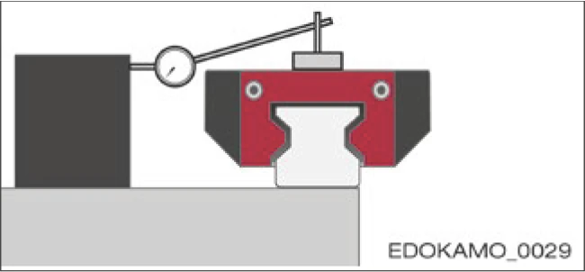
Characteristics:
- No reference edge available
- Manual alignment using tools such as alignment rules, guide bars, dial indicators, installation carriages
- Medium to high accuracy level depending on complexity
Method 3: Alignment Using Lateral Reference
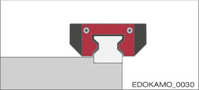
Characteristics:
- Lateral reference in machine bed
- Alignment by pressing against locating surface
- High accuracy level, depending on reference edge precision
- Minimum time required
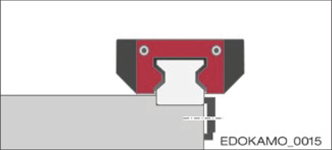
Method 4: Alignment Using Lateral Locating Surface Plus Additional Clamping
Characteristics:
- Lateral locating surface and additional lateral clamping
- Alignment by pressing against locating surface using lateral clamping components
- Very high accuracy level, depending on reference edge precision
- Minimum time required
4.12.3 Lateral Locating Surfaces and Clamping for Carriages
When installing SCHNEEBERGER MONORAIL guideways using lateral locating surfaces, it is recommended that the opposite side of guide rails and carriages also be secured using clamping elements. This makes guide rail alignment easier and supports high lateral force absorption in both directions. Different clamping elements can be used for lateral clamping. The transmittable lateral force depends highly on the respective design and needs to be checked on a case-by-case basis.

Adjusting screws and clamping bars / Single or double wedge bars / Countersunk screw shafts / Eccentric screws
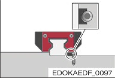
Clamping element with tapered chamfer
4.12.4 Installation Methods
When selecting the appropriate installation method and determining the number and arrangement of locating surfaces, different criteria must be considered. These include:
- Loads
- Required accuracy
- Assembly effort
- Specific installation environment
Load Considerations
Forces in the tension/compression direction do not have any effect on lateral locating surfaces. If loads occur from the side and exceed the permissible lateral force values without locating surfaces (see Section 4.9 - Guide Rail Mounting and Section 4.11 - Carriage Fastening), locating surfaces must be provided, and where applicable, lateral clamping. The number and direction depend on the forces occurring. Locating surfaces should be arranged according to the main load force direction. When vibration and impact occur, lateral locating surfaces should also be provided. Otherwise, increase the rigidity of the system.
Accuracy Considerations
In cases where strict guide rail accuracy is required, the use of lateral locating surfaces is recommended. Locating surfaces make installation easier and reduce the complexity of achieving accuracy. Guide rail accuracy is determined by the straightness of the locating surfaces and the precision of the guide rail pressing process and/or lateral clamping.
Assembly Effort
Locating surfaces make installation easier and reduce the complexity required to align guide rails.
Through careful manual alignment of guide rails, lateral locating surfaces can be omitted. When deciding on the method, the complexity of installation should be carefully weighed against the complexity of design and technical manufacturing.
Specific Installation Environment
Locating surfaces and lateral clamping require additional installation space and access to installation locations. Therefore, it is important to check whether the provided locating surfaces and clamping are compatible with the installation location in the machine. Some typical installation methods are listed below:
Typical Installation Methods

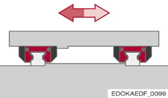
Method 1
- No locating surfaces
- Small lateral force absorption from the side, forces transmitted through friction locking
- High assembly effort
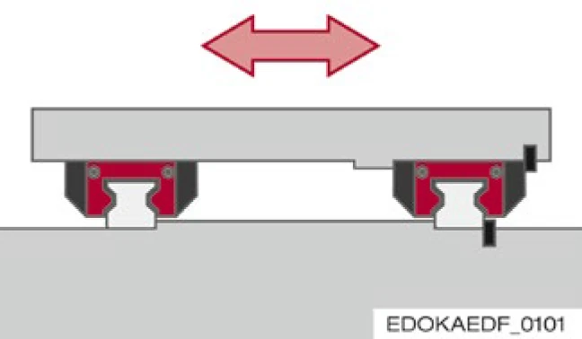
Method 2
- Two guide rails each with one locating surface, one carriage side with opposing locating surface
- Simple installation
- High lateral force absorption from one direction, e.g., for inclined bed axes or suspended installation

Method 3
- One guide rail and its carriages with locating surface and lateral clamping
- For high lateral forces from both directions, one guide rail and its carriages absorb most lateral forces
- Relatively simple installation
Method 4
- Two guide rails and one carriage side with locating surfaces, one guide rail and its carriages also with lateral clamping
- Simple installation
- High lateral force absorption from both directions

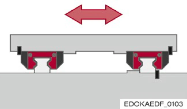
Method 5
- Two guide rails and one carriage side with locating surfaces and lateral clamping
- Simple installation
- Very high accuracy level
- For very high lateral forces from both directions
Method 6
- One guide rail and two carriage sides with locating surfaces and lateral clamping
- Simple installation
- Very high accuracy level
- For very high lateral forces from both directions
4.12.5 Geometric and Positional Accuracy of Support Surfaces
The performance of SCHNEEBERGER MONORAIL guideways can only be achieved when installed on rigid structures with high geometric accuracy. Inaccuracies in connecting surfaces are partially compensated by elastic deformation of the MONORAIL guideway, but may affect overall accuracy, running behavior, thrust, and service life. Unstable connecting surfaces increase internal constraint forces in the guideway, which also adversely affects service life.
When the following tolerances for height deviation and parallelism are observed, the impact on service life is negligible in practice.
Surface Quality of Connecting Surfaces
The surface quality of support surfaces does not directly affect the function and running behavior of the guideway, but does affect static accuracy. Carriages and guide rails are pressed onto the locating surfaces by high-force screw connections. To prevent settlement behavior of the connection, a high surface contact rate is required. This is achieved through a high level of surface quality. For support and locating surfaces, an average surface roughness of Ra 0.4 to 1.6 μm is recommended.
Permissible Deviations in Lateral Direction
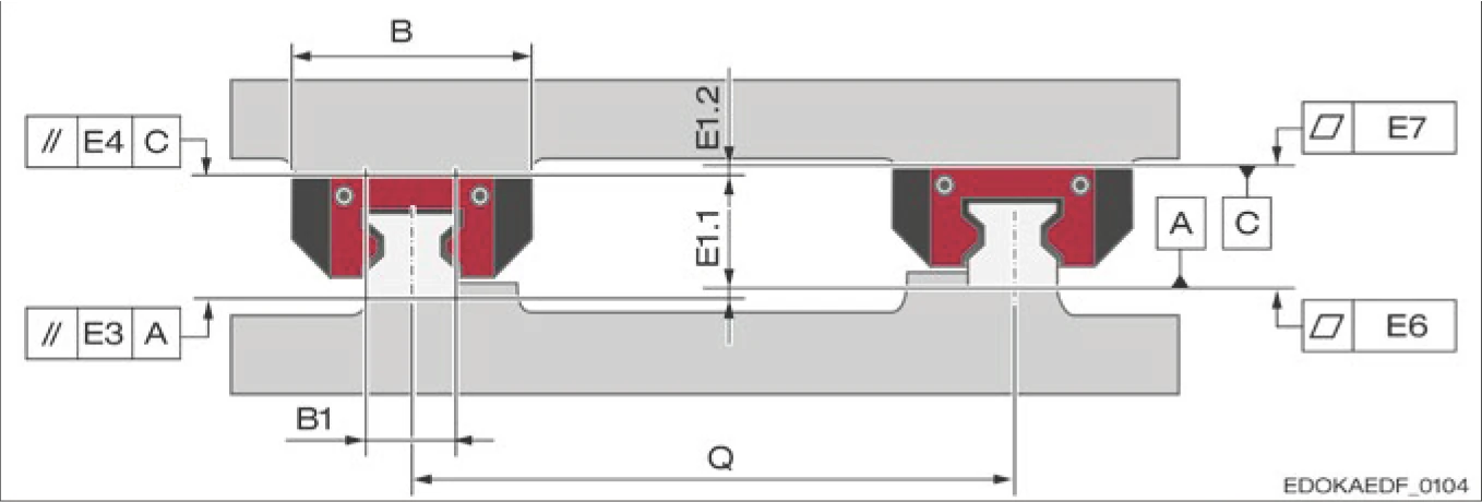
Symbols for Permissible Deviations in Lateral Direction:
- B: Carriage width (mm)
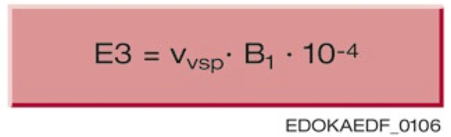
- B1: Guide rail width (mm)
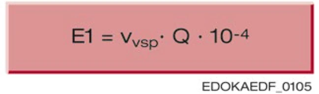
- E1: Lateral height deviation
- E3: Lateral parallelism of guide rail support surface
- E4: Lateral parallelism of carriage support surface
- E6: Flatness of guide rail support surface
- E7: Flatness of carriage support surface
- Q: Guide rail spacing system (mm)
Lateral Height Deviation Calculation
E1 = E1.1 + E1.2
This also includes the tolerance of dimension A = MONORAIL height.
Lateral Parallelism of Guide Rail Support Surface E3
Lateral Parallelism of Carriage Support Surface E4

Preload Factor
The preload factor describes the influence of preload on the accuracy requirements for carriage and guide rail support surfaces. Higher preload means higher rigidity, and therefore greater internal forces are generated when deviations occur in the connecting surfaces.
| Preload | V0 / V1 | V2 | V3 |
|---|---|---|---|
| Preload factor vsp | 3.0 | 2.0 | 1.0 |
Permissible Deviations in Longitudinal Direction
Symbols for Permissible Deviations in Longitudinal Direction:
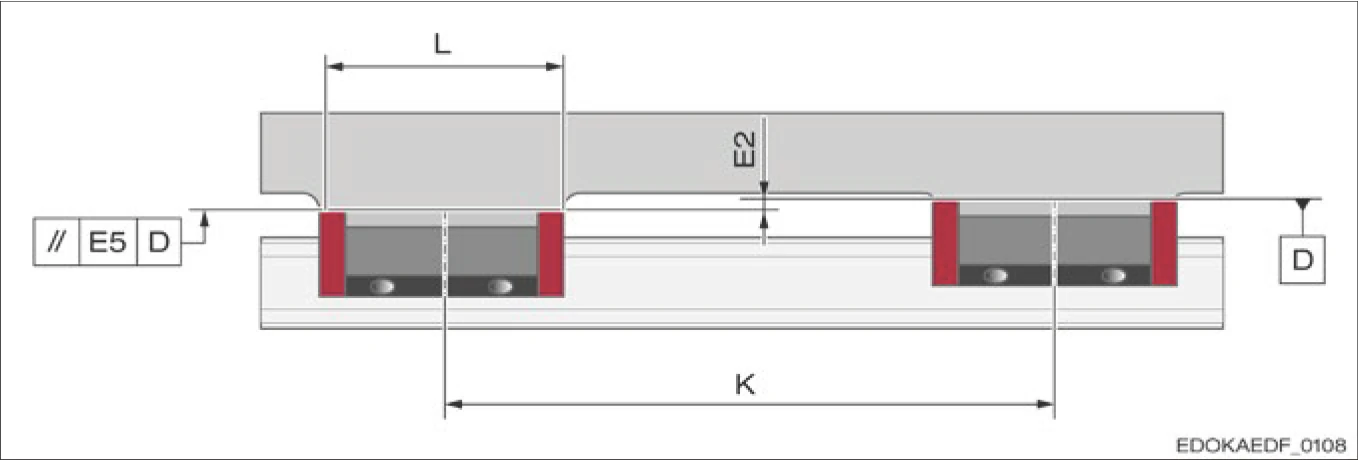
- E2: Longitudinal height deviation
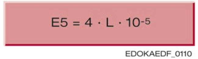
- E5: Longitudinal parallelism of carriage support surface
- L: Total carriage length
- K: Carriage longitudinal spacing
- Δh: Height difference between carriage 1 and carriage 2
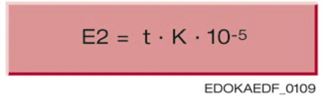
Carriage Factor
Carriage factor t:
- MRA/C and BMA/C/F = 5
- MRB/D and BMB/D/G = 4
Longitudinal Parallelism of Carriage Support Surface E5
Permissible Parallelism Tolerances for Locating Surfaces
For non-parallel aligned guide rails, stroke movement causes tension in the guideway system, which adds additional load to the rolling contact surfaces. This can lead to reduced service life. Otherwise, it reduces the running accuracy of the guideway.
Therefore, the specified parallelism tolerance Δ should be observed, assuming infinite rigidity of the carriage seat.

Tolerance Δ (μm) for Preload Classes V0 - V3
| Size | V0 | V1 | V2 | V3 |
|---|---|---|---|---|
| 15 | 13 | 12 | 11 | 6 |
| 20 | 13 | 12 | 11 | 6 |
| 25 | 14 | 13 | 12 | 7 |
| 30 | 16 | 15 | 14 | 8 |
| 35 | 18 | 17 | 16 | 9 |
| 45 | 22 | 21 | 20 | 11 |
| 55 | — | 25 | 23 | 13 |
| 65 | — | 29 | 27 | 17 |
| 100 | — | 35 | 33 | 20 |
Flatness of Locating Surfaces
For the flatness E6 of guide rail support over the entire length, it is recommended to use the running accuracy values of the accuracy class from the diagram in Section 3 - Running Accuracy as a guide.
The flatness E7 of carriage support should not exceed the values listed in the table below.
Flatness E7 of Carriage Support for MR Guideway Series
| Size | Flatness (μm) |
|---|---|
| 25 | 0.5 |
| 30 | 0.8 |
| 35 | 0.8 |
| 45 | 1 |
| 55 | 1 |
| 65 | 2 |
| 100 | 2 |
Important Notes
- The accuracy of connecting surfaces directly affects the performance and service life of the guideway system
- Recommended surface roughness Ra 0.4 to 1.6 μm
- Parallelism and flatness tolerances must be strictly observed
- Higher preload classes require stricter support surface accuracy