Wall Thickness Specifications
The wall thickness of mineral castings typically must be at least five times the maximum aggregate particle size. With a standard aggregate particle size of 16mm, the minimum wall thickness is 80mm.
Due to low residual stress, the material allows different wall thickness variations without problems. Non-load-bearing sections can use finer mineral mixtures to achieve thinner wall thicknesses through pre-casting procedures.
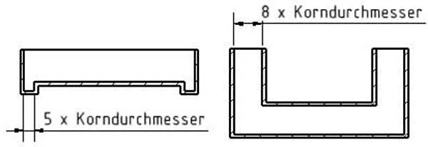
With standard aggregate particle size of 16mm, standard wall thickness is 80mm.
Wall Thickness and Material Correspondence Table
| Material Model | Max. Aggregate Particle Size | Min. Wall Thickness |
|---|---|---|
| SCHQ10 | 16 mm | 80 mm |
| SCHQ30 | 12 mm | 60 mm |
| SCHQ40 | 8 mm | 40 mm |
| SCHQ50 | 4 mm | 20 mm |
| SCHQ100 | — | 5-10 mm (coating) |
| FS80 | 16 mm | 80 mm |
Draft Angle Design
Draft angle design is similar to gray cast iron, but mineral casting allows smaller angles than the traditional casting standard of 5°.
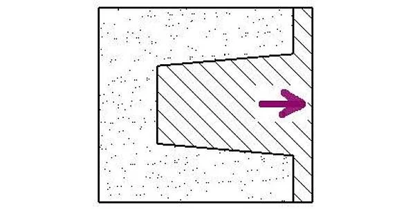
Standard Draft Angle
Applicable to most vertical surfaces
Mineral Casting Advantage
Smaller draft angles possible compared to gray cast iron
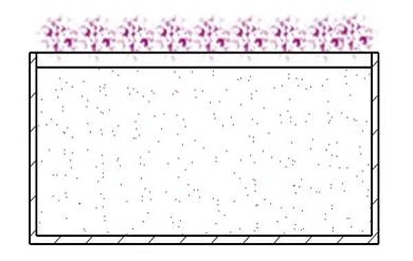
Ventilation System Design
Air enters during the mixing process and becomes trapped during casting. After pouring the mixture, the mold needs to be vibrated until almost no air bubbles rise, to prevent shrinkage cavities.
Proper mold ventilation requires well-arranged positions to avoid obstructing material flow or air escape, especially on horizontal surfaces where bubbles easily form.

Load Capacity Design
Mineral casting components can withstand higher compressive and tensile forces than alternative materials. Anchor points must maintain sufficient distance from edges to prevent cracking.


Screw Connection Evaluation
Thread load capacity needs to be evaluated, metal thread inserts may be required.
Fillets and Chamfers
Fillets and chamfers reduce stress concentration effects.
Transportation Considerations
Large components require consideration of lifting points (crane handling) and forklift channels.
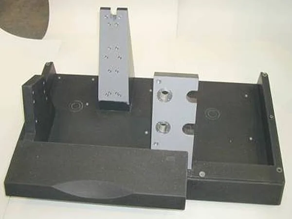
Basic Geometric Structure
Molds can be made from wood, steel, aluminum, PVC, silicone, polyamide, or composite materials. Selection criteria include:

Key Point: Main functional surfaces require special attention to geometric accuracy and rigidity design.
Mechanical Component Integration
Threaded inserts, steel plates, transport anchors, cables, and hollow units can be cast directly into components during the cold casting process. Secure fixing prevents position changes caused by buoyancy during casting.
Components too close to edges or requiring matching hole patterns can use specially formed cast parts and be anchored with hex screws.


Integratable Components
- Threaded inserts
- Steel plates
- Transport anchors
- Cable channels
- Hollow units
Working Surface Accuracy
Using high-quality molds, typical accuracy can reach approximately ±0.1 mm/m. Surfaces that need to mate with other parts require higher accuracy. Four main procedures can achieve specified tolerances:

Mechanical Processing
Mineral casting reserved machining allowance, then milled/ground to precise dimensions.
Embedded Metal Processing
Metal elements cast in, then mechanically processed after hardening.
Replica Casting
First cast approximately 2mm undersize, then precision cast using fine material in second stage.
Post-casting Metal Parts
Cast metal parts using positioning gauges after demolding.
FEM Finite Element Analysis
Finite element method calculations can determine component geometric characteristics, mechanical design deformation, and derive optimized geometries. Temperature dynamics and vibration response calculations have now reached high precision.

Practical Application Examples
- Reducing deflection in textile machinery
- Reducing regenerative effects in lathes through excellent mineral casting absorption characteristics (compared to welded or cast designs)
Professional Services: SCHNEEBERGER can provide FEM analysis services to help optimize design solutions.
Transportation and Installation

Transportation
When using cranes, forklifts, and vehicles for transportation, appropriate anchors and rails for secure fixing are required.
Installation
Installation principles are similar to steel or cast iron bases. Large machines benefit from large engine foundations providing 70-90% of total machine mass, ensuring high torsional rigidity and inertia mass while achieving necessary precision.
Correct dimensional design prevents partial sinking and loss of workspace geometric accuracy. Three-point mounting configuration is an exception, with accuracy not dependent on the foundation.
Custom Material Solutions
Professional developers create various formulations for individual customer applications, providing the optimal combination of technical benefits and cost.

Design Consultation: SCHNEEBERGER technical team can provide professional consultation during the design phase, helping optimize design solutions and select the most suitable material formulations.