Permissible Speed Calculation
Permissible Speed Calculation
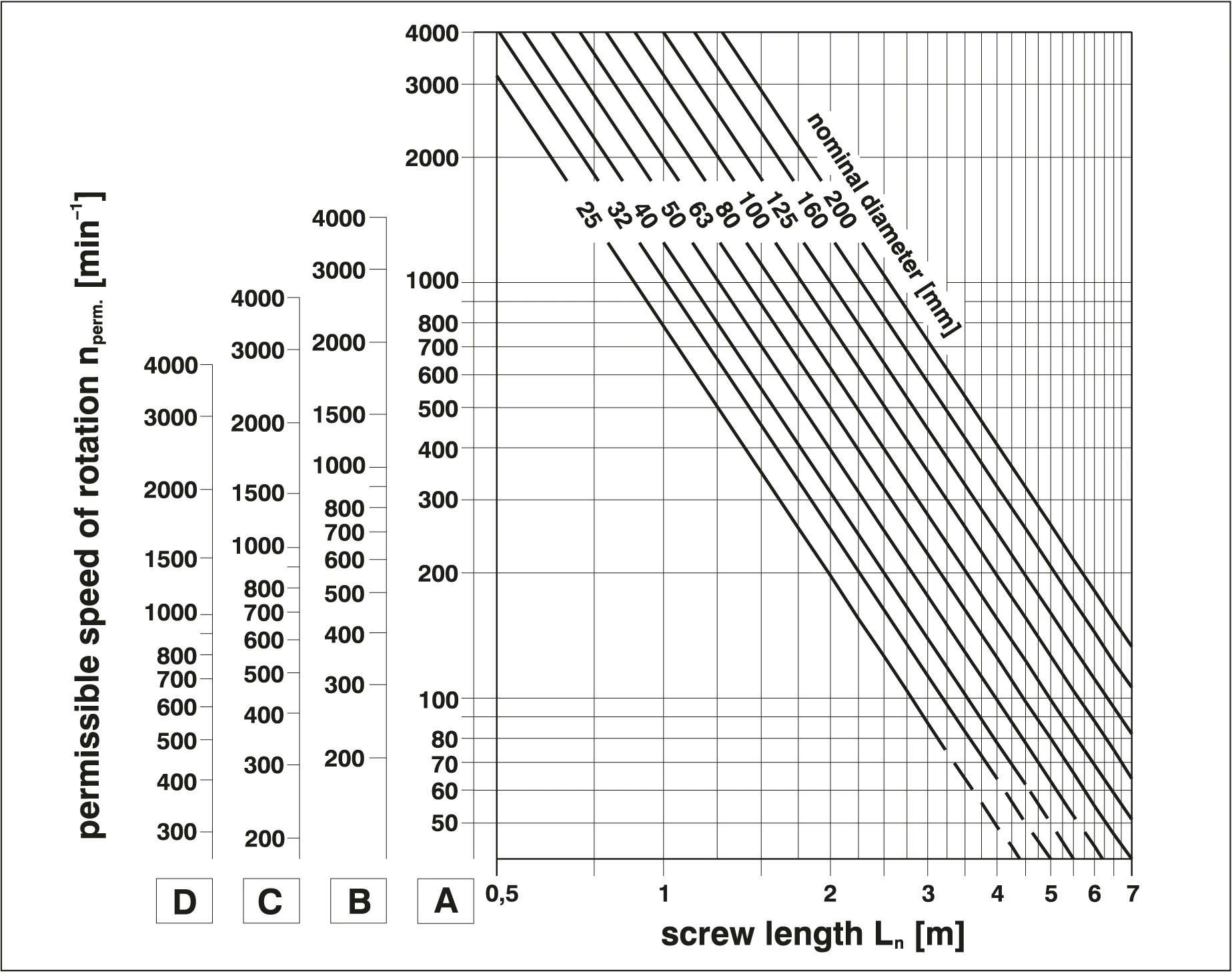
Calculated values should be regarded as approximations. For precise calculations, please contact us.
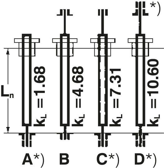
*) Directionally stable mounting
Transverse Resonant Vibration Transverse Resonant Vibration
Any shaft exceeding the permissible speed will excite transverse resonant vibration. On ball screws, this causes excessive radial loads on the nut system.
Safety Factor
The maximum permissible speed is 80% of the critical speed (20% below critical speed). This safety factor has been incorporated into the calculation chart above.
Importance of Bearing Arrangement Importance of Bearing Arrangement
The specific implementation of screw bearings has a significant impact on the permissible speed.
See data sheets for d0, dk
Screw Sagging Problem
Inadmissible Sagging of Screw
High Slenderness Ratio Screw Considerations
When the slenderness ratio Ln/d0 > 50, additional support must be provided in the free area of the thread length to prevent sagging. Otherwise, the ball screw will be operating under inadmissible conditions.
Note: This is equally important for driven nut systems!
Limit Application Consultation
When Ln/d0 > 40, please contact us for professional advice.
Slenderness Ratio Reference Table
Slenderness Ratio Reference
| Ln/d0 Range | Recommended Action |
|---|---|
| ≤ 40 | Standard design, no additional support required |
| 40 - 50 | Consultation recommended, special design may be required |
| > 50 | Additional support required to prevent sagging |
Symbol Reference
Symbol Reference
| Symbol | Description |
|---|---|
| Ln | Thread length |
| d0 | Nominal diameter |
| nperm | Permissible speed |
| ncrit | Critical speed |