AM Ball Screws - Manufacturing Drawing
Manufacturing Drawing - Economic Design Recommendations
Economic Design Recommendations
Design Key Points
| Item | Recommendation |
|---|---|
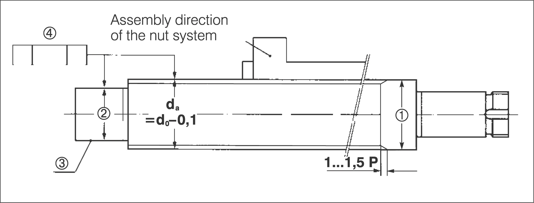
| 1. Flange Diameter | Flange diameter ≦ screw outer diameter da. Avoid flange diameter larger than da if possible. |
| 2. Shaft Diameter | Shaft diameter on at least one side of the thread for nut assembly, d = dk = d0 - ball diameter - 0.5 (also applies to undercut grooves). |
| 3. Deep Nitriding | AM ball screws have deep nitrided bearing seats. Please identify all surfaces that must remain unhardened. Fine pitch threads always remain unhardened. |
| 4. Geometric Tolerances | Geometric tolerances according to DIN 69051. |
| 5. Series Design | Provide screws of different lengths - with the same nominal diameter and lead - with identical screw ends and nuts ("part families"). |
| 6. Standard Nuts | Consider nuts conforming to German standard DIN, preferably AM standard 2.51 or 2.52. |
Drawing Specification Requirements
Please include the following performance characteristics in your drawings:
| Characteristics | Symbol | Value / Option | Unit |
|---|---|---|---|
| Nominal diameter | d0 | mm | |
| Nominal lead | P | mm | |
| Direction of lead | L.H. (Left-hand) R.H. (Right-hand) | ||
| ISO precision class | IT type | ||
| Tolerance of specified lead | ±ep | µm/lu | |
| Variation | V300p | µm | |
| Type of nut system (abbr.) | type No. | ||
| Nut rigidity | Rnu | kN/µm | |
| - No-load torque without wipers | Tpr0 | Nm | |
| - Preload | Fpr | kN | |
| Mean load | Fm | kN | |
| Mean speed of rotation | nm | min-1 | |
| Max. speed of rotation | nmax | min-1 | |
| Acceleration | a | m/sec² | |
| Moved mass | m | kg | |
| Lubrication | |||
| Mounting position | Horizontal Vertical | ||
| Driven element | Nut Screw |
Design Checklist
Drawing Review Points
- Confirm flange dimensions do not exceed screw outer diameter
- Check shaft diameter meets nut assembly requirements
- Mark areas that need to remain unhardened
- Confirm geometric tolerances conform to DIN 69051
- Consider using standard nuts to reduce costs
- For series products, unify screw end design