AMS Magneto-Resistive Measuring Principle
Magneto-resistive Measuring Method
Scale Manufacturing
The scale contains two magnetic tracks:
- Precision incremental track: Alternating N poles and S poles, with a pitch of 200 um
- Reference track: For determining absolute position, with options for multiple points, equidistant reference points, or single reference point

Manufacturing Process
The scale is fully integrated into the rail section. The manufacturing process is as follows:
| Step | Description |
|---|---|
| 1 | A slot is ground into the finished rail section |
| 2 | Magnetic material strip is inserted into the slot |
| 3 | Magnetic material is ground and magnetized |
| 4 | A through-hardened, magnetically permeable cover is welded to the rail to protect the measuring scale |
Protective Design
This cover design protects the measuring scale from chips and coolant. The measuring scale position is consistent across all AMS product series.
Magneto-Resistive Position Sensor
When relative motion occurs between the sensor and measuring scale, changes in magnetic field strength in the magneto-resistive material cause resistance changes that are easy to measure.
Wheatstone Bridge Sensor Element
The circuit design of Wheatstone bridge sensor elements minimizes the effects of temperature fluctuations, aging, and external magnetic field interference.
Signal Generation
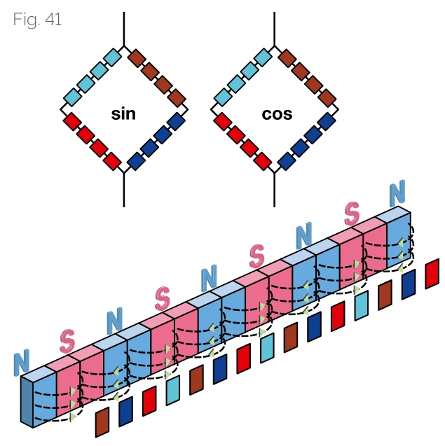
Due to the arrangement of sickle-shaped sensor elements, two sinusoidal waveform signals with 90-degree phase offset are obtained from the incremental magnetization.
Precision Enhancement
To improve precision, signals from 104 individual elements are averaged along the measurement direction. Since the sensor structure adapts to the magnetic division period, the influence of external magnetic field interference is greatly suppressed.
Sensor Position Independence
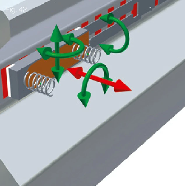
All measurement signal characteristics that determine precision (phase, amplitude difference, harmonic characteristics, etc.) are fixed within the sensor. Therefore, even with significant deviations in sensor position and tilt, signal quality is not degraded: "The circuit remains stable".
Direct Benefits
- Easy Replacement: Read heads can be simply replaced without any adjustment
- Enhanced Vibration Resistance: Stronger resistance to vibration and shock
- Wide Tolerance Band: Read head operation has a wide tolerance band
Automatic Gain Control (AGC) Operation
Current amplitude (represented by periodic signal) is continuously determined in the electronic measuring system. When any deviation occurs, amplitude is automatically adjusted. Therefore, even under abnormal conditions (installation errors, external errors, or carriage removal), standardized output signals are provided.
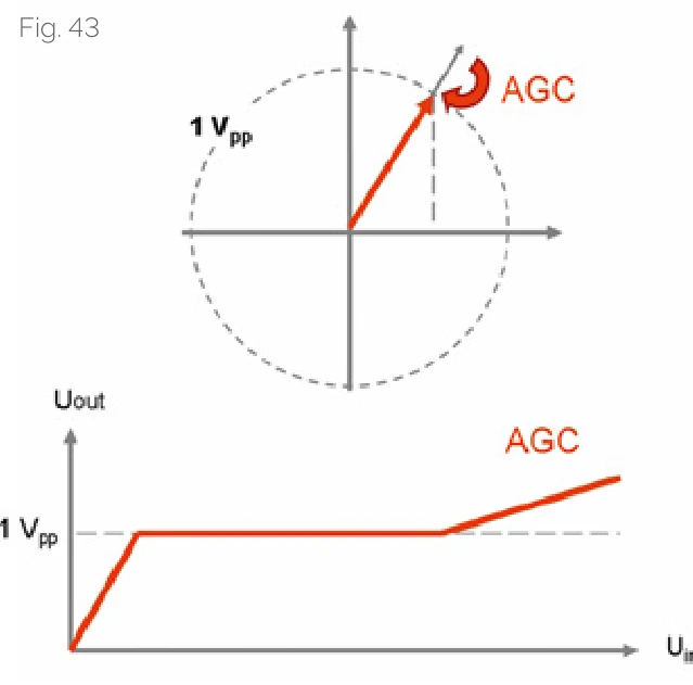
AGC Functions
| Amplitude Monitoring | Continuously monitors current amplitude of periodic signal |
| Automatic Adjustment | Automatically adjusts amplitude when deviation occurs |
| Abnormal Handling | Provides stable output even under installation errors, external errors, or slider removal conditions |
Reference Point Identification
The second track carries AMS reference marks for determining absolute position and system zeroing. Reference point accuracy is critical for the machine's zero or home position.
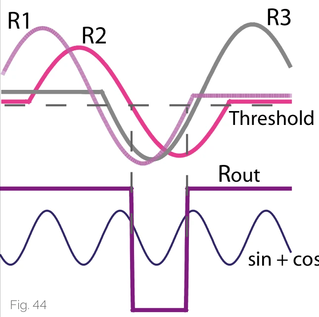
Reference Point Operating Principle
One reference point is represented by three magnetic reference marks on the reference point magnetization:
- The rising edge of the reference pulse represents one reference information
- The falling edge of the reference pulse represents another reference information
- The third reference information is redundant design to improve the operational reliability of the reference point identification system
This operating principle suppresses any magnetic interference and does not provide a reference signal when interference is encountered, ensuring system reliability.
Features and Options
Magnetization Options
AMS MONORAIL products offer different reference point options, these marks are laser engraved on the surface. The diagram below shows the position of the first reference point.

Reference Point Types
| Code | Type | Description |
|---|---|---|
| TR50 | 50mm Reference Point Grid | AMS system with reference points every 50 mm |
| TD50 | Multiple Origin | AMS system with multiple origins. Origin spacing: 50.2 / 49.8 / 50.4 / 49.6 / 50.6 / 49.4 / ... mm (50mm encoding pattern) |
Read Head Position and Mounting Side
In the order code, SCHNEEBERGER indicates the read head mounting position, measuring scale position, and reference sides of rails and carriages. For vertical drawings, rotate the diagram 90 degrees counterclockwise. The following information must be included when ordering:
Rail Mounting Side and Measuring Scale Position
| Code | Rail Reference Side | Measuring Scale Position |
|---|---|---|
| R11 | Reference bottom | Scale bottom |
| R12 | Reference bottom | Scale top |
| R21 | Reference top | Scale bottom |
| R22 | Reference top | Scale top |
Read Head Position
| Code | Description |
|---|---|
| P1 | External mounting, housing right, reading head top |
| P3 | External mounting, housing left, reading head bottom |
Carriage Mounting Side
| Code | Description |
|---|---|
| R1 | Reference bottom |
| R2 | Reference top |
Ordering Notes
When ordering an AMS measuring system, the configuration codes for rail reference side, measuring scale position, read head mounting position, and carriage reference side must be clearly specified to ensure correct system installation and operation.