1.3.1 Load Capacity
The load capacity of profiled rail guideways is expressed as load capacity values. These values provide the basis for product selection, and are calculated according to DIN ISO 14728-1 (dynamic load capacity) and DIN ISO 14728-2 (static load capacity).
Load capacity represents the force or load that a guideway can withstand before permanent damage occurs. The magnitude of load capacity is determined by the following factors:
- Number of loaded rolling element rows
- Number of loaded rolling elements per row
- Rolling element diameter
- Rolling element length (for rollers)
- Contact angle
- Material
- Raceway surface hardness
SCHNEEBERGER MONORAIL guideways can withstand forces from all directions as well as moments about all axes. Load capacity is divided into two types: dynamic load capacity and static load capacity.

Forces and moments on the carriage
Symbol explanation:
Moments
Load Capacity
Load Capacity Types
Dynamic Load Capacity C
Applies to guideways in motion, used for calculating service life.
Static Load Capacity C0
Applies to stationary or slowly moving guideways, used for evaluating maximum allowable load.
Load capacity values always relate to the load capacity of a single carriage. When using multiple carriages on one axis, load capacity does not multiply, as rigid applications do not allow for uniform load distribution among carriages.
Important Note
Due to the non-uniform nature of actual load distribution, when designing with multiple carriages, appropriate safety factors should be used in calculations. Please refer to product specification sheets for load capacity values of each product.
1.3.2 Dynamic Load Capacity C
Dynamic load capacity C is defined as the constant load under which rolling contact can achieve a travel life of 100,000 meters. This is essential data required for calculating the service life of rolling element contacts.
Service Life Calculation
The service life of rolling contacts can be calculated using the following formula:
L = (C / P)p × 100,000 m
L = Travel life (meters)
C = Dynamic load capacity (N)
P = Equivalent dynamic load (N)
p = Life exponent (balls = 3, rollers = 10/3)
Conversion of Dynamic Load Capacity for Different Travel Lives
The dynamic load capacity C in SCHNEEBERGER catalogs is based on 100,000 meters travel life (C100). If values based on 50,000 meters travel life are needed, the following conversion formula can be used:

Conversion of dynamic load capacity
C50 = 1.23 × C100 (ball guideways)
C50 = 1.26 × C100 (roller guideways)
1.3.3 Static Load Capacity C₀
Static load capacity C₀ (N) is an important characteristic parameter in SCHNEEBERGER MONORAIL guideway design. It is used to verify the static safety factor.
According to DIN ISO 14728-2, static load capacity C₀ is defined as the force corresponding to a plastic deformation at the rolling element-raceway contact equal to 0.0001 times the rolling element diameter.
Static load capacity indicates the load limit of guideways at rest or during slow movement. During operation, it must be ensured that guideways do not experience forces exceeding the static load capacity. This also applies to short-duration events such as vibrations or impacts.
Important Consideration
Even brief vibration or impact loads must not exceed the static load capacity. Exceeding this limit may cause permanent deformation of rolling elements and raceways, affecting guideway performance and accuracy.
Static Safety Factor S₀
The static safety factor S₀ is a protection value against impermissible permanent deformation of rolling elements and raceways. It is defined as the ratio of static load capacity C₀ to static equivalent force P₀:

Static safety factor S₀
S0 = C0 / P0
S0 = Static safety factor
C0 = Static load capacity (N)
P0 = Static equivalent force (N)
Determination of P₀
For P₀, the actual forces acting on the rolling contact surface must be considered. The determining factor for rolling contact surface deformation is the highest amplitude, which may occur even in very short periods.
Recommended Safety Factors
Depending on requirements and operating conditions, the following minimum values for static safety factor S₀ are recommended:
| Operating Conditions | Recommended S₀ |
|---|---|
| Normal operation with minimal vibration | ≥ 1.5 |
| Moderate alternating loads and vibration | ≥ 2.0 |
| High impact loads and vibration | ≥ 3.0 |
| High dynamic stress, high impact loads and vibration | ≥ 5.0 |
Design Recommendation
For specific calculation methods, please refer to Section 4.10 - Calculation and Selection. In practical design, appropriate safety factors should be selected based on specific operating conditions of the application.
1.3.4 Static and Dynamic Moments
The allowable static moment M₀ is the moment that produces a load equal to the static load capacity C₀ on the carriage. Similarly, the allowable dynamic moment M corresponds to the dynamic load capacity C.
Allowable dynamic moments are critical for guideway design, particularly regarding transverse moment MQ and longitudinal moment ML loads on the carriage. Transverse and longitudinal moments increase the overall guideway load, and must be correspondingly considered when calculating service life and static safety factor S₀. See Section 4.10 - Calculation and Selection.
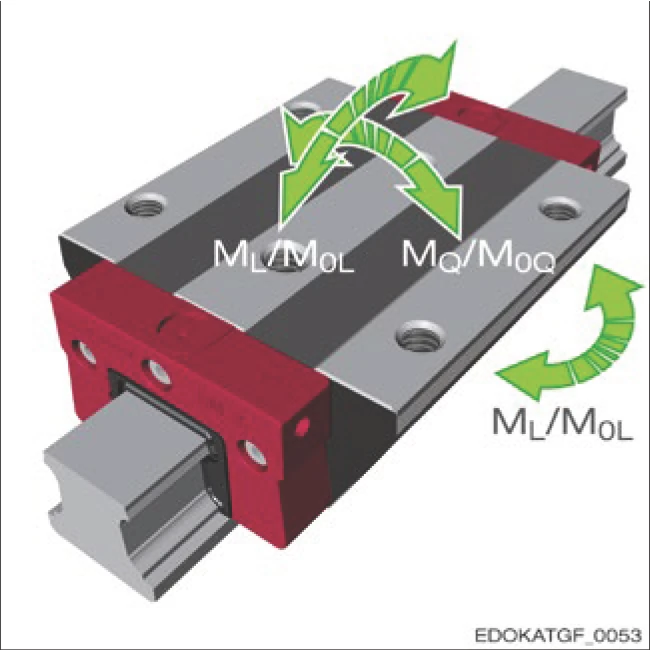
Moments on the carriage
Moment symbol explanation:
Dynamic Moments
Static Moments
Longitudinal Moment ML
The magnitude of allowable longitudinal moment ML depends primarily on the number of rolling elements per row, and therefore also on the length of the carriage. Long carriages can withstand higher moments than short carriages. In this process, the load on individual rolling elements is distributed from the outer edges toward the carriage center.
Longitudinal Moment ML / M0L
Moment rotating about the longitudinal axis of the guideway. Moment magnitude depends on carriage length and number of rolling elements per row.
Transverse Moment MQ / M0Q
Moment rotating about the transverse axis of the guideway. Moment magnitude depends on raceway spacing and geometric configuration.
Transverse Moment MQ
In addition to carriage length, raceway spacing is also crucial for the magnitude of allowable transverse moment MQ. With so-called O-geometry, raceway spacing is larger than with X-geometry guideways. See Section 1.2 - Construction of Profiled Rail Guideways.
Limitation of Static Transverse Moment M0Q
Static transverse moment M0Q is only related to rolling contact deformation. However, the maximum allowable transverse moment of profiled rail guideways is also limited by the screw connection of carriage and guideway. See Section 4.11.7 - Guide Rail Installation - Allowable Tensile Force and Transverse Torque.
Moment Characteristics of SCHNEEBERGER MONORAIL
In SCHNEEBERGER MONORAIL guideways, four raceways are configured at 90° to each other. This results in equally high load capacity for longitudinal moments about the transverse axis (ML) and vertical axis.
Due to the O-geometry of the guideways, a large raceway spacing is achieved, resulting in high load capacity for moments about the longitudinal axis (MQ). Specific values for each product can be found in the SCHNEEBERGER MONORAIL and AMS product catalog.
Design Key Points
- Long carriages (B, D, and G types) perform best in rigidity under force and moment loads due to having many loaded rolling elements
- Transverse and longitudinal moments increase overall guideway load and must be considered when calculating service life
- Screw connection strength may limit maximum allowable transverse moment
1.3.5 Load Direction
The static (C₀) and dynamic (C) load capacities in SCHNEEBERGER MONORAIL and AMS product catalogs are specified for the load direction of tensile/compressive/lateral forces.

Load directions at different angles (0°, 90°, 180°, 270°)
Relationship Between Load Capacity and Angle
If guideways are loaded at different angles, load capacity decreases. The reason lies in the internal force absorption method. Ideally, forces are absorbed by 2 raceways. In the worst case, when the load angle is below 45°, only one raceway bears the load.
Effect of 45° Load Direction
Load capacity reduces to approximately 70% of original value
Service life reduces to approximately 30%

Influence of the direction of force on the service life: Roller guideway MR (red) and ball guideway BM (yellow)
Effect on Service Life
The load capacity and service life of SCHNEEBERGER MONORAIL guideways depend on load direction. When calculating service life, the combined equivalent force P needs to be used to account for this factor.
Force Resolution
Geometrically, for inclined force directions, based on the total load Fres shown in the figure below, the horizontal force component FY and vertical force component FZ are added by vector addition to act on the carriage.

Vector addition of the horizontal FY and vertical FZ force components for the total load Fres
Equivalent Force Formula
Conversely, given the equivalent force P, force components are algebraically added using the following formula:

Equivalent force formula
P = |FY| + |FZ|
P = Equivalent force
FY = Horizontal force component (Y-direction force)
FZ = Vertical force component (Z-direction force)
Therefore, for forces different from the main direction, the dynamic equivalent force is always greater than the actual force acting on the guideway. This method allows the dynamic load capacity C to always be used in the service life formula, while accounting for the reduced load capacity due to inclined load directions and the associated reduction in service life. See Section 4.10 - Calculation and Selection.
Service Life Formula
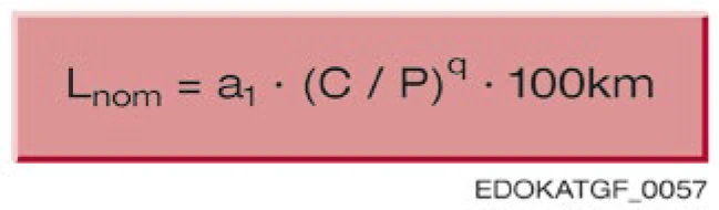
Nominal service life formula
Lnom = a1 × (C / P)q × 100 km
Lnom = Nominal service life
C = Dynamic load capacity
P = Equivalent force
a1 = Service life adjustment factor
q = Service life calculation exponent (rollers = 10/3, balls = 3)
Service Life Loss Due to Inclined Loads
Service life loss due to inclined loads can be significant because the calculation includes the ratio C/P with an exponent q ≈ 3. In the worst case, when the force angle is below 45°, service life is reduced by approximately 2/3 compared to main direction loading.
Design Recommendation
Therefore, when designing axes, ensure that guideways are configured according to the main load direction to achieve maximum service life.
Load Configuration Principles
Fundamentally, guideways should be configured so that occurring forces are distributed as uniformly as possible on the carriage, with the main load acting in the tensile/compressive direction. The advantage is that forces can be directly absorbed by the guideway and transferred to the surrounding structure through fixing screws. High lateral forces in some cases generate moments acting on the guideway, which can only be transmitted through additional locating surfaces in the connecting structure, creating additional costs.