MR Size 30 Technical Specifications
Medium-high load applications in compact spaces
Rail Types MR S 30
| MR S 30-N | MR S 30-NU |
|---|---|
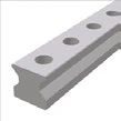 |  |
| Standard Top mounting | Bottom threaded hole Bottom mounting |
Size 30 Features
Size 30 is positioned between Size 25 and Size 35, suitable for applications requiring higher load capacity in limited space. Available in N (Standard) and NU (Bottom threaded hole) rail types.
Rail Dimensional Drawing MR S 30

Rail Specifications MR S 30
| Parameter | MR S 30-N | MR S 30-NU |
|---|---|---|
| Rail Width B1 (mm) | 28 | 28 |
| Rail Height J1 (mm) | 28 | 28 |
| Max. Single Length L3 (mm) | 6000 | 6000 |
| Hole Pitch L4 (mm) | 40 | 40 |
| First/Last Hole Position L5/L10 (mm) | 18.5 | 18.5 |
| Weight per Unit (kg/m) | 4.6 | 5.2 |
Model Designations
- N = Standard (top mounting)
- NU = Bottom threaded hole (bottom mounting)
Carriage Types MR W 30
| MR W 30-A | MR W 30-B | MR W 30-C | MR W 30-D | MR W 30-F | MR W 30-G |
|---|---|---|---|---|---|
 |  |  |  |  |  |
| Standard Standard | Standard long Standard long | High/flat High/flat | High/flat long High/flat long | Flat Flat | Flat long Flat long |
Size 30 Carriage Note
Size 30 offers six carriage types (A, B, C, D, F, G), not including E type (side fixing).
Carriage Dimensional Drawing MR W 30

Carriage Specifications MR W 30
| Parameter | MR W 30-A | MR W 30-B | MR W 30-C | MR W 30-D | MR W 30-F | MR W 30-G |
|---|---|---|---|---|---|---|
| System Height A (mm) | 42 | 42 | 45 | 45 | 42 | 42 |
| Carriage Width B (mm) | 90 | 90 | 60 | 60 | 60 | 60 |
| Reference Distance B2 (mm) | 31 | 31 | 16 | 16 | 16 | 16 |
| Front Center Lube Port C1 (mm) | 6 | 6 | 9 | 9 | 6 | 6 |
| Side Lube Port Position C3 (mm) | 6 | 6 | 9 | 9 | 6 | 6 |
| Side Lube Port Position C4 (mm) | 16 | 26.5 | 22 | 22.5 | 22 | 22.5 |
| Top Lube Port Position C7 (mm) | 16 | 26.5 | 22 | 22.5 | 22 | 22.5 |
| Carriage Height J (mm) | 35.5 | 35.5 | 38.5 | 38.5 | 35.5 | 35.5 |
| Carriage Length L (mm) | 108 | 129 | 108 | 129 | 108 | 129 |
| Transverse Wiper Distance La (mm) | 103 | 124 | 103 | 124 | 103 | 124 |
| Outer Hole Pitch L1 (mm) | 52 | 52 | 40 | 60 | 40 | 60 |
| Inner Hole Pitch L2 (mm) | 44 | 44 | - | - | - | - |
| Steel Body Length L6 (mm) | 70 | 91 | 70 | 91 | 70 | 91 |
| Side Hole Pitch N (mm) | 72 | 72 | 40 | 40 | 40 | 40 |
| Reference Height O (mm) | 8 | 8 | 8 | 8 | 8 | 8 |
| Carriage Weight (kg) | 1.1 | 1.5 | 0.9 | 1.2 | 0.8 | 1.0 |
Rigidity Curves and Load Rating Diagrams

Load Ratings
| Carriage Type | C0 Static Load (N) | C100 Dynamic Load (N) | M0Q Static Cross Moment (Nm) | M0L Static Long. Moment (Nm) | MQ Dynamic Cross Moment (Nm) | ML Dynamic Long. Moment (Nm) |
|---|---|---|---|---|---|---|
| A / C / F | 74,900 | 39,500 | 1,332 | 966 | 702 | 510 |
| B / D / G | 98,500 | 48,900 | 1,751 | 1,614 | 869 | 801 |
Load Rating Definitions
- C0 = Static load capacity - Maximum allowable load causing permanent deformation
- C100 = Dynamic load capacity - Load for 100km travel life
- M0Q / MQ = Cross moment - Rotation around travel axis
- M0L / ML = Longitudinal moment - Rotation around vertical axis
Available Options
Accuracy Classes
| Accuracy Class | Carriage & Rail Tolerance A/B2 | Max. Deviation Paired Carriages | Max. Deviation Standard Carriages |
|---|---|---|---|
| G0 Highly accurate | +/- 5 um | 3 um | 10 um |
| G1 Very accurate | +/- 10 um | 5 um | 20 um |
| G2 Accurate | +/- 20 um | 7 um | 40 um |
| G3 Standard | +/- 30 um | 25 um | 60 um |
Preload Classes
| Preload Class | Preload Force (% of C0) | Applications |
|---|---|---|
| V0 Very light preload | 0-2% | Very low friction, uniform load, minimum vibration |
| V1 Light preload | 3% | Low friction, uniform load, slight vibration |
| V2 Medium preload | 8% | High rigidity, moderate varying loads and vibration |
| V3 High preload | 13% | Maximum rigidity, impact loads, severe varying loads |
Surface Treatment (Coating)
| Code | Type | Features |
|---|---|---|
| - | Standard (uncoated) | Standard steel surface |
| CN | Hard chromium | Excellent corrosion protection, high wear resistance, good emergency running properties |
Reference Side Position
R1 - Reference at bottom R2 - Reference on top
Order Code Examples
Rail Order Code
MR S 30-N-G1-KC-R1-800-18.5-18.5-CN
- MR S 30 = MONORAIL Rail Size 30
- N = Standard type
- G1 = High precision
- KC = Countersunk holes
- R1 = Reference at bottom
- 800 = Rail length 800mm
- 18.5-18.5 = First/last hole positions
- CN = Hard chrome plating
Carriage Order Code
MR W 30-A-G1-V2-R1-CN-S11-LV
- MR W 30 = MONORAIL Carriage Size 30
- A = Standard type
- G1 = High precision
- V2 = Medium preload (8% C0)
- R1 = Reference at bottom
- CN = Hard chrome plating
- S11 = Lubrication port at top center
- LV = Full grease fill as delivered