4.7.1 Selection Criteria
The installation method describes the orientation and arrangement of the individual guide rails relative to each other in the guideway system. Different criteria must be considered when selecting the installation variant, including:
- Application type
- Forces and moments occurring
- Accuracy requirements
- Rigidity requirements
- Operating conditions, such as degree of contamination
- Type of lubrication
- Available installation space
- Assembly effort
- Consideration of temperature changes occurring in components and associated additional forces
- Consideration of screw connections used on the axis
- Consideration of additional fall protection devices for suspended axes
Basically, the guide rails should be arranged so that the occurring forces are distributed as evenly as possible on the carriages and the main load acts in the tension/compression direction. The advantage of this is that the forces are absorbed directly by the guide rails and can be transferred to the surrounding structure via the fixing screws. High lateral forces in some cases lead to moments acting on the guide rail and can only be transferred from additional locating surfaces in the connecting structure, which incurs additional costs.
In terms of lubricating and protecting the guide rails, horizontally or vertically arranged guide rails should be preferred over other arrangements. With regard to assembly and guide rail accuracy, it is recommended that all guide rails be arranged on only one plane.
4.7.2 Installation Variants
Some typical installation methods and their respective characteristics and features are listed below.
In most examples, a dual guide rail configuration with two carriages per guide rail is most common, as this configuration is most widely used in practical applications. The screw direction and lateral fixing methods for guide rails and carriages are not included in the examples. These topics are explained in more detail in the following sections: Section 4.11 - Fixing Guide Rails, Section 4.13 - Fixing Carriages, and Section 4.14 - Configuration of Connecting Structures.
Configuration 1: Single Rail Configuration
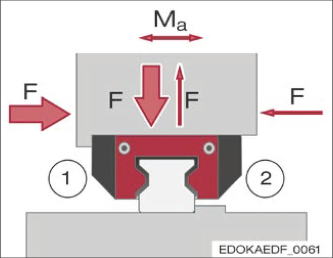
- One guide rail with one or two carriages
- Horizontal installation
- Minimum moment load capacity Ma
- Suitable for manual axes and auxiliary axes with low loads
- Simple alignment adjustment
- High lateral force absorption capacity on locating surface (1)
- Low lateral force absorption capacity on counter-locating surface (2)
Configuration 2: Dual Rail Standard Configuration

- Two guide rails, each with two carriages
- Horizontal installation
- Simple installation
- High accuracy class
- Suitable for various types of axes, traveling columns
- Simple alignment using reference rail (1)
- High moment load capacity Ma
Configuration 3: Inclined Installation (45°)

- Inclined installation, e.g., tilted 45° about longitudinal axis
- High force absorption capacity in the inclined angle direction
- Oil lubrication requires separate treatment
- Guide rails tend to accumulate dirt (use covers if necessary)
- Suitable for slant bed lathes
- Accumulation of dirt and coolant in upper prism:
- Special covers required
- Drainage holes/channels required
Configuration 4: Suspended Installation (90° Wall Mount)

- Suspended installation, tilted 90° (wall assembly)
- High level of horizontal force absorption capacity
- Oil lubrication requires separate treatment
- Guide rails tend to accumulate dirt
- Suitable for lathes, machining center lateral slides
- Accumulation of dirt and coolant in upper prism:
- Special covers required
- Drainage holes/channels required
Configuration 5: Guide Rails Offset 90° Configuration

- Horizontal installation, guide rails offset 90°
- High moment rigidity
- Precise installation adjustment
- Suitable for lateral slides of gantry machine tools
- Strict accuracy requirements for locating surfaces
Configuration 6: Inverted Installation (Suspended Axis)
- Installation rotated 180°, suspended axis
- Reduced rigidity due to tensile load
- Carriages tend to accumulate dirt
- Higher static safety factor required
- Fall protection must be provided
- Screw load recalculation required
Configuration 7: Multi-Rail Parallel Configuration
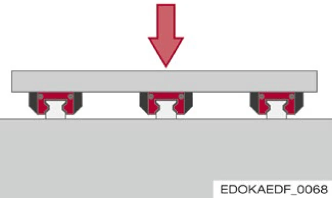
- Horizontal installation
- Multiple guide rails side by side, each with three or more carriages
- (Carriage height must be kept within small tolerance)
- High vertical force absorption capacity and rigidity
- Suitable for machine tool work tables with extremely high forces
- Large spacing required between outer guide rails
- Support plates required to prevent sagging
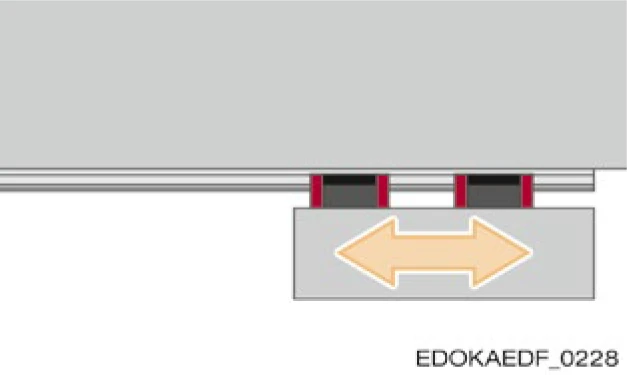
Configuration 8: Guide Rail Rotated 180° (Fixed Carriage)
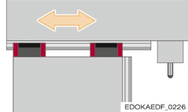
- Guide rail rotated 180°, carriage fixed
- Horizontal installation (guide rail extends into machining chamber, may be damaged by chips. Solution: hardened guide rail surface)
- Suitable for cantilever axes and support beams
- Suitable for horizontal milling/drilling machines, EDM machines
- Carriages tend to accumulate dirt
Configuration 9: Closely Arranged Dual Rail Configuration

- 2 guide rails and carriages closely arranged each
- High vertical force absorption capacity
- Suitable for gantry machine tools
- Due to rigid surrounding structure, high accuracy class and/or matched design carriages required
Configuration 10: Close Carriage Configuration Under Main Force

- Medium-sized carriages closely arranged under main force
- Insufficient connecting plate rigidity
- Outer carriages additionally loaded due to plate sagging. Solution: rigid connecting plate
- Suitable for heavy machine tools
- High accuracy class and/or matched design carriages required
- Horizontal installation
Caution
Carriages May Separate from Guide Rail
- Carriages may separate from guide rails, so additional safety functions must be implemented for carriages, for example in the form of safety clamps around the guide rail to prevent separation.
Users need to take appropriate design and technical safety measures to prevent separation of carriages and guide rails in the event of errors (e.g., due to loss of rolling elements).
One possible design measure variant is a safety clamp around the guide rail. The regulations of the relevant professional associations, relevant guidelines, and standards for the application involved should also be observed.