Proper carriage fastening is essential for the performance of SCHNEEBERGER MONORAIL guideway systems. This chapter provides detailed information on carriage fastening methods, locating surface design, permissible lateral forces, screw specifications, and key factors affecting system rigidity.
4.11.1 Fastening Methods
MONORAIL carriages, depending on model and size, have fixing holes in positions according to DIN 645 standard for fastening to the connecting structure. Type A and B designs have combined threaded fixing holes, while compact types C, D, E, F, and G have blind fixing holes. For maximum carriage rigidity, it is recommended to use all fixing holes. See Chapter 3.
Fastening from Above
Fastening using threaded holes
Fastening using threaded holes
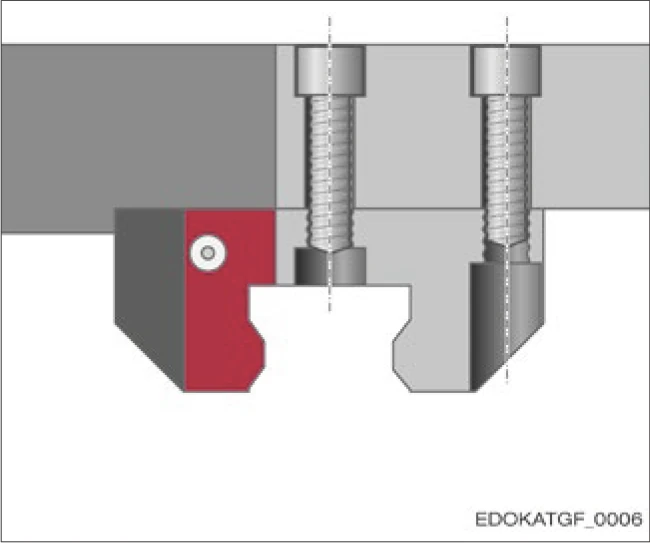
All carriages can be fastened from above using threaded fixing holes. This is the recommended method. Because threading allows larger diameter screws, a stronger joint can be formed.
When using the middle fixing hole, remove any plastic protective plugs first. Pay attention to the length of the middle fixing screw to avoid damaging the guide rail.
Fastening from Below

Fastening using threaded holes
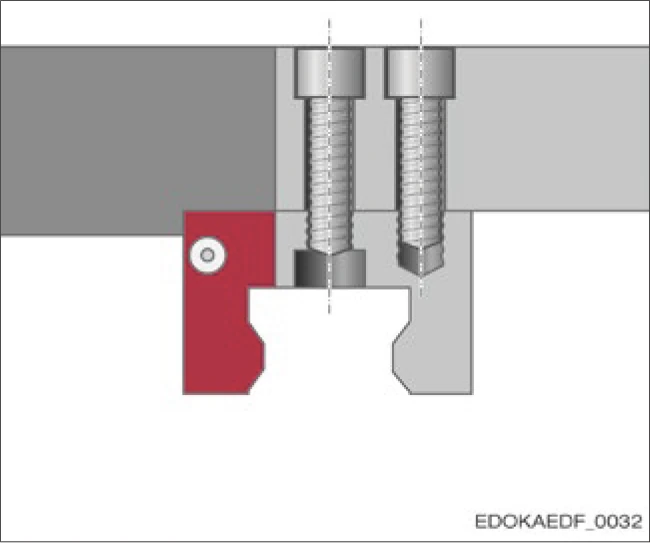
Type A and B carriages can also be fastened from below, using the threaded fixing holes as through holes with correspondingly smaller diameter screws. In this case, the middle fixing hole must use low-head screws according to DIN 6912. If using two middle mounting holes, plastic protective plugs must be removed if present.
4.11.2 Lateral Locating Surfaces
Standard Reference Edge
Carriages are supplied as standard with a ground locating surface on one side. This is defined by dimension B2.

Standard reference edge configuration
Double Reference Edge
Both sides of the carriage have ground surfaces. The primary locating surface of MR carriages is identified by the "A" marking on the side. The primary locating surface of BM carriages is identified by the longitudinal groove. The primary locating surface is defined by dimension B2. The second locating surface is dimensioned relative to the primary locating surface. The two locating surfaces are not symmetrically positioned at the carriage center relative to dimension B2.

Double reference edge configuration
Locating Surface Identification
- MR Carriages: "A" marking on the side indicates the primary locating surface
- BM Carriages: Longitudinal groove indicates the primary locating surface
- The second locating surface has a specific position tolerance relative to the primary locating surface
4.11.3 Permissible Lateral Force Without Locating Surface
Guide values for maximum permissible lateral force without locating surface can be referenced from the table below.
FSide_max values depend on the dynamic load capacity C, carriage fastening method, and screw strength class.
Maximum Lateral Force per Carriage
By size and number of DIN 912/ISO 4762 fixing screws:
| Specification | M4 (Size 15) | M5 (Size 15, 20) | M6 (Size 20, 25) | M8 (Size 25-35) | ||||
|---|---|---|---|---|---|---|---|---|
| 4 Screws | 6 Screws | 4 Screws | 6 Screws | 4 Screws | 6 Screws | 4 Screws | 6 Screws | |
| Strength Class 8.8 | 1250 | 1900 | 2100 | 3150 | 2950 | 4450 | 5400 | 8100 |
| Strength Class 12.9 | 2150 | 3250 | 3550 | 5300 | 5000 | 7500 | 9200 | 13800 |
| Specification | M10 (Size 30-45) | M12 (Size 45, 55) | M14 (Size 55, 65) | M16 (Size 65) | ||||
|---|---|---|---|---|---|---|---|---|
| 4 Screws | 6 Screws | 4 Screws | 6 Screws | 4 Screws | 6 Screws | 4 Screws | 6 Screws | |
| Strength Class 8.8 | 8600 | 13000 | 12600 | 19000 | 17300 | 26000 | 23900 | 35800 |
| Strength Class 12.9 | 14600 | 21900 | 21300 | 32000 | 29300 | 44000 | 40300 | 60400 |
| Specification | M16 (Size 100) | M20 (Size 100) | ||
|---|---|---|---|---|
| 6 Screws | 9 Screws | 6 Screws | 9 Screws | |
| Strength Class 8.8 | 35800 | 53700 | 55100 | 82700 |
| Strength Class 12.9 | 60400 | 90600 | 92000 | 138100 |
4.11.4 Effect of Number of Fixing Screws on Rigidity
This diagram illustrates the relationship between guideway rigidity and the number and quality of fixing screws per carriage. Particularly under tensile loads, when the number of screws is reduced from 6 to 4, elastic deformation increases significantly.

Effect of carriage fastening on rigidity illustrated using O-type 4-row ball guideway as example. Relationship between force F (kN) and deformation δ (μm) under tension and compression.
Diagram Legend:
- Curve 1: 4 screws, strength class 8.8
- Curve 2: 4 screws, strength class 12.9
- Curve 3: 6 screws, strength class 8.8
- δ: Deformation under force F
- F: Applied force
Rigidity Improvement Recommendations
- Using all available fixing holes can significantly increase system rigidity
- Using strength class 12.9 screws can further improve performance
- In high-load applications, 6-screw configuration is recommended
4.11.5 Permissible Screw Tightening Torques
Maximum tightening torques for fixing screws according to ISO 4762 are shown in the table below. This is based on a friction coefficient μ = 0.125 in the as-delivered condition.
Caution
Components may be damaged if screws are not tightened with correct torque
- Recommendations of the screw supplier must be followed and are binding.
- DIN 6912 low-head screws should be tightened according to strength class 8.8
- If tension loss is expected, secure the screws
Tightening Torques for ISO 4762 Fixing Screws
To improve fracture resistance in the event of moving axis collision, linear guideways should use screws with strength class 12.9 according to ISO 898-1 whenever possible. However, screws with strength class 8.8 to 12.9 can generally be used.
| Maximum Tightening Torque (Nm) | ||||||||
|---|---|---|---|---|---|---|---|---|
| Screw | M4 | M5 | M6 | M8 | M10 | M12 | M14 | M16 |
| Size | (15) | (15, 20) | (20, 25) | (25-35) | (30-45) | (45, 55) | (55) | (65) |
| Strength Class 8.8 | 3 | 6 | 10 | 25 | 49 | 83 | 130 | 200 |
| Strength Class 12.9 | 5 | 10 | 16 | 40 | 81 | 95 | 166 | 265 |
| Screw | M20 |
|---|---|
| Size | (100) |
| Strength Class 8.8 | 410 |
| Strength Class 12.9 | 680 |
4.11.6 Minimum Screw Engagement Depth
The screw length required for carriage fastening can be determined based on the thickness of the carriage or machine slide and the minimum screw engagement depth, for example according to VDI 2230 guidelines. For carriage dimensions, see the SCHNEEBERGER MONORAIL and AMS product catalog.
Screw Length Calculation
Screw length = Carriage thickness + Minimum engagement depth + Safety margin
Minimum engagement depth should follow VDI 2230 standards or screw manufacturer recommendations.