
With its type R, SCHNEEBERGER has developed the first standardized cross roller guide, which has defined the global industry standard.
The RD double V-shaped guide supplements the R linear guideway and supports space-saving and cost-effective solutions.
Download R Series CAD ModelsType R Benchmark Data
Track and surface quality
- Precision ground supporting and/or locating surfaces and tracks (90° V-profile)
Materials (standard)
- Rails from through hardened tool steel 1.2842, hardness 58 – 62 HRC
- The sizes R/RD 1 and 2 are made out of tool steel 1.3505
- For non-corrosive guideways tool steel 1.4034 and 1.4112 is used
- Rolling element made of through hardened roller bearing steel, hardness 58 – 64 HRC
Rolling elements
- Balls or rollers
Velocity
- 1 m/s
Acceleration
- 50 m/s²
Accuracy
- R and RD linear guideways are available in three quality classes (see chapter 9)
Operating temperatures
- -40°C to +80°C
Combinable products
- R and RD designs can be combined with:
- Recirculating units type SK, SKC and SR
Type R Dimensions and Load Capacities

| Type | Size | L | Dimensions (mm) | Options (see chapter 7) | Accessories | ||||||||||||||
|---|---|---|---|---|---|---|---|---|---|---|---|---|---|---|---|---|---|---|---|
| in mm | Weight in g | A | B/B2 | Dw | J | L1 | L2 | N | d | e | e1 | f | g | m | q | ||||
| R | 1 | 20 | 3 | 8.5 | 4 | 1.5 | 3.9 | 10 | 5 | 1.8 | M2 | M1.6 | M1.6 | 1.65 | 2.6 | 1.9 | 2.5 | SQ SSQ RF EG ZG HA DU | Cages • AA-RF 1 • AC 1 • AK 1 End screw • GA 1 End piece • GB 1 |
| 30 | 4 | ||||||||||||||||||
| 40 | 5 | ||||||||||||||||||
| 50 | 6 | ||||||||||||||||||
| 60 | 7 | ||||||||||||||||||
| 80 | 9 | ||||||||||||||||||
| 100 | 12 | ||||||||||||||||||
| 120 | 14 | ||||||||||||||||||
| R | 2 | 30 | 8 | 12 | 6 | 2 | 5.5 | 15 | 7.5 | 2.5 | M3 | M2.5 | M2.5 | 2.55 | 4 | 2.7 | 3.5 | SQ SSQ RF EG ZG HA DU | Cages • AA-RF 2 • AC 2 • AK 2 End screw • GA 2 End piece • GB 2 Fastening screw • GD 3 |
| 45 | 11 | ||||||||||||||||||
| 60 | 14 | ||||||||||||||||||
| 75 | 17 | ||||||||||||||||||
| 90 | 20 | ||||||||||||||||||
| 105 | 23 | ||||||||||||||||||
| 120 | 26 | ||||||||||||||||||
| 150 | 34 | ||||||||||||||||||
| 180 | 40 | ||||||||||||||||||
| R | 3 | 50 | 23 | 18 | 8 | 3 | 8.3 | 25 | 12.5 | 3.5 | M4 | M3 | M3 | 3.3 | 4.8 | 4.1 | 7 | SQ SSQ RF EG ZG HA DU | Cages • AA-RF 3 • AC 3 • AK 3 End screw • GA 3 End pieces • GB 3 • GC 3 • GC-A 3 Fastening screw • GD 3 • GD 4 |
| 75 | 34 | ||||||||||||||||||
| 100 | 45 | ||||||||||||||||||
| 125 | 56 | ||||||||||||||||||
| 150 | 67 | ||||||||||||||||||
| 175 | 78 | ||||||||||||||||||
| 200 | 89 | ||||||||||||||||||
| 225 | 100 | ||||||||||||||||||
| 250 | 111 | ||||||||||||||||||
| 275 | 122 | ||||||||||||||||||
| 300 | 133 | ||||||||||||||||||
| 350 | 155 | ||||||||||||||||||
| 400 | 178 | ||||||||||||||||||
| 500 | 222 | ||||||||||||||||||
| 600 | 267 | ||||||||||||||||||

| Type | Size | L | Dimensions (mm) | Options (see chapter 7) | Accessories | ||||||||||||||
|---|---|---|---|---|---|---|---|---|---|---|---|---|---|---|---|---|---|---|---|
| in mm | Weight in g | A | B/B2 | Dw | J | L1 | L2 | N | d | e | e1 | f | g | m | q | ||||
| R | 6 | 100 | 145 | 31 | 15 | 6 | 13.9 | 50 | 25 | 6 | 9.5 | M6 | M5 | 5.2 | 9.8 | 6.9 | 9 | SQ SSQ RF EG ZG HA DU | Cages • AA-RF 6 • AC 6 • AK 6 End screw • GA 6 End pieces • GB 6 • GC 6 • GC-A 6 Fastening screw • GD 6 • GD 9 |
| 150 | 220 | ||||||||||||||||||
| 200 | 295 | ||||||||||||||||||
| 250 | 370 | ||||||||||||||||||
| 300 | 445 | ||||||||||||||||||
| 350 | 520 | ||||||||||||||||||
| 400 | 595 | ||||||||||||||||||
| 450 | 670 | ||||||||||||||||||
| 500 | 745 | ||||||||||||||||||
| 600 | 895 | ||||||||||||||||||
| 700 | 1045 | ||||||||||||||||||
| 800 | 1195 | ||||||||||||||||||
| 1000 | 1500 | ||||||||||||||||||
| R | 9 | 200 | 630 | 44 | 22 | 9 | 19.7 | 100 | 50 | 9 | 10.5 | M8 | M6 | 6.8 | 15.8 | 9.8 | 9 | SQ SSQ RF EG ZG HA DU | Cages • AC 9 • AK 9 • EE 9 End screw • GA 9 End pieces • GB 9 • GC 9 • GC-A 9 Fastening screw • GD 9 • GD 12 |
| 300 | 945 | ||||||||||||||||||
| 400 | 1260 | ||||||||||||||||||
| 500 | 1575 | ||||||||||||||||||
| 600 | 1890 | ||||||||||||||||||
| 700 | 2205 | ||||||||||||||||||
| 800 | 2520 | ||||||||||||||||||
| 900 | 2835 | ||||||||||||||||||
| 1000 | 3150 | ||||||||||||||||||
| 1100 | 3465 | ||||||||||||||||||
| 1200 | 3780 | ||||||||||||||||||
| 1400 | 4410 | ||||||||||||||||||
| R | 12 | 200 | 1040 | 58 | 28 | 12 | 25.9 | 100 | 50 | 12 | 13.5 | M10 | M8 | 8.5 | 19.8 | 12.9 | 12 | SQ SSQ RF EG ZG HA DU | Cages • AC 12 • AK 12 End screw • GA 12 End pieces • GB 12 • GC 12 • GC-A 12 Fastening screw • GD 12 • GD 15 |
| 300 | 1560 | ||||||||||||||||||
| 400 | 2090 | ||||||||||||||||||
| 500 | 2615 | ||||||||||||||||||
| 600 | 3140 | ||||||||||||||||||
| 700 | 3665 | ||||||||||||||||||
| 800 | 4190 | ||||||||||||||||||
| 900 | 4715 | ||||||||||||||||||
| 1000 | 5240 | ||||||||||||||||||
| 1100 | 5765 | ||||||||||||||||||
| 1200 | 6290 | ||||||||||||||||||

| Type | Size | L | Dimensions (mm) | Options (see chapter 7) | Accessories | ||||||||||||||
|---|---|---|---|---|---|---|---|---|---|---|---|---|---|---|---|---|---|---|---|
| in mm | Weight in g | A | B | B1 | B2 | Dw | J | L1 | L2 | Q | d | e | f | g | k | ||||
| RD | 1 | 100 | 50 | 22 | 4 | 5.5 | 6 | 1.5 | 12.8 | 25 | 12.5 | 13.5 | 4.4 | M3 | 2.55 | 3.5 | 2 | SQ SSQ RF EG ZG HA DU | Cages • AA-RF 1 • AC 1 • AK 1 Fastening screw • GD 3 |
| 150 | 70 | ||||||||||||||||||
| 200 | 100 | ||||||||||||||||||
| RD | 2 | 200 | 220 | 30 | 6 | 8.5 | 9 | 2 | 17 | 50 | 25 | 18 | 6 | M4 | 3.35 | 5.4 | 3 | SQ SSQ RF EG ZG HA DU | Cages • AA-RF 2 • AC 2 • AK 2 Fastening screw • GD 3 • GD 4 |
| 300 | 320 | ||||||||||||||||||
| 400 | 430 | ||||||||||||||||||
| RD | 3 | 300 | 690 | 46 | 8 | 11.5 | 12 | 3 | 26.6 | 50 | 25 | 28 | 7.5 | M5 | 4.2 | 7.3 | 4 | SQ SSQ RF EG ZG HA DU | Cages • AA-RF 3 • AC 3 • AK 3 Fastening screw • GD 4 • GD 6 |
| 400 | 920 | ||||||||||||||||||
| 500 | 1150 | ||||||||||||||||||
| 600 | 1380 | ||||||||||||||||||
| 800 | 1840 | ||||||||||||||||||

| Type | Size | L | Dimensions (mm) | Options (see chapter 7) | Accessories (a) | ||||||||||||||
|---|---|---|---|---|---|---|---|---|---|---|---|---|---|---|---|---|---|---|---|
| in mm | Weight in g | A | B | B1 | B2 | Dw | J | L1 | L2 | Q | d | e | f | g | k | ||||
| RD | 6 | On request | On request | 76 | 15 | 19 | 20 | 6 | 41.8 | 100 | 50 | 45 | 9.5 | M6 | 5.2 | 13.8 | 5 | SQ SSQ RF EG ZG DU | Cage: - AA-RF 6 - AC 6 - AK 6 Fastening screw: - GD 6 - GD 9 |
| RD | 9 | Max. 3000 | On request | 116 | 22 | 27 | 28 | 9 | 67.4 | 100 | 50 | 72 | 10.5 | M8 | 6.8 | 20.8 | 6 | SQ SSQ RF EG EE ZG DU | Cage: - AC 9 - AK 9 - EE 9 Fastening screw: - GD 9 |
| RD | 12 | Max. 3000 | On request | 135 | 28 | 34 | 35 | 12 | 70.8 | 100 | 50 | 77 | 13.5 | M10 | 8.5 | 25.8 | 7 | SQ SSQ RF EG ZG DU | Cage: - AC 12 - AK 12 Fastening screw: - GD 12 - GD 15 |
Maximum Lengths for Type R
| Type / Size | Quality class | Max. lengths in standard material (in mm) | Max. lengths in non-corrosive material (in mm) |
|---|---|---|---|
| R 1 | NQ | 200 | 150 |
| SQ | 200 | 150 | |
| SSQ | 120 | 120 | |
| R 2 | NQ | 300 | 300 |
| SQ | 300 | 300 | |
| SSQ | 180 | 180 | |
| R 3 | NQ | 800 | 600 |
| SQ | 800 | ||
| SSQ | 600 | 600 | |
| R 6 | NQ | 1500 | 1400 |
| SQ | 1500 | 1200 | |
| SSQ | 1200 | 900 | |
| R 9 | NQ | 3000 | 3000 |
| SQ | |||
| SSQ | |||
| R 12 | NQ | 3000 | 3000 |
| SQ | |||
| SSQ | |||
Maximum Lengths for Type RD
| Type / Size | Quality class | Max. lengths in standard material (in mm) | Max. lengths in non-corrosive material (in mm) |
|---|---|---|---|
| RD 1 | NQ | 300 | 300 |
| SQ | |||
| SSQ | |||
| RD 2 | NQ | 500 | 500 |
| SQ | |||
| SSQ | |||
| RD 3 | NQ | 1200 | 600 |
| SQ | |||
| SSQ | |||
| RD 6 | NQ | 1500 | 900 |
| SQ | 1200 | ||
| SSQ | |||
| RD 9 | NQ | 3000 | 3000 |
| SQ | |||
| SSQ | |||
| RD 12 | NQ | 3000 | 3000 |
| SQ | |||
| SSQ | |||
Rail Chamfer
The diagrams below show the rail chamfer in detail. Please note that the part number and company logo are marked on the opposite position of the reference and support surfaces.
| Type / Size | Rail chamfer of reference edges in mm |
|---|---|
| R 1 | 0.3 x 45° |
| R 2 | 0.3 x 45° |
| R 3 | 0.6 x 45° |
| R 6 | 0.8 x 45° |
| R 9 | 0.8 x 45° |
| R 12 | 1.0 x 45° |
Accessories for Type R and RD
Roller Cage Type AC
Compatible with:
- Linear guideway type R and RD, Sizes 1 to 12
Features:
- Rollers fixed in place
Installation method:
- Suitable for normal applications and certain overtravel cage applications
Material:
- Sizes 1, 2: POM
- Size 3: PA GF 30%
- From size 6: PA GF 30%, plastic/steel wire composite construction. Steel wire made of stainless steel.
- Non-corrosive rollers

| Type | Size | Dw | d | e | t | w | C100 per roller in N | C50 per roller in N | max. length in mm |
|---|---|---|---|---|---|---|---|---|---|
| AC | 1 | 1.5 | 0.45 | 3.5 | 3 | approx. 1.5 | 50 | 61.50 | 80 |
| 2 | 2 | 0.75 | 5 | 4 | approx. 2 | 85 | 104.55 | 170 | |
| 3 | 3 | 1 | 7 | 5 | approx. 2.5 | 130 | 159.90 | 1'200 | |
| 6 | 6 | 2.5 | 14 | 9 | approx. 6 | 530 | 651.90 | 1'500 | |
| 9 | 9 | 3.5 | 20 | 14 | approx. 9 | 1'300 | 1'599.00 | 1'500 | |
| 12 | 12 | 4.5 | 25 | 18 | approx. 11 | 2'500 | 3'075.00 | 1'500 |
Roller Cage Type AA-RF
Compatible with:
- Linear guideway type R and RD, Sizes 1, 2, 3 and 6
Features:
- Rollers fixed in place
Installation method:
- Not suitable for use as overtravel cage
Material:
- Cage and rollers made of non-corrosive steel, therefore also suitable for vacuum environments

| Type | Size | Dw | d | e | t | w | C100(1) per roller in N | C50(1) per roller in N | max. length in mm |
|---|---|---|---|---|---|---|---|---|---|
| AA-RF | 1 | 1.5 | 0.2 | 3.8 | 3 | approx. 1.5 | 44 | 54.12 | 90 |
| 2 | 2 | 0.25 | 5.9 | 4 | approx. 2 | 75 | 92.25 | 150 | |
| 3 | 3 | 0.3 | 7.5 | 5 | approx. 2.5 | 115 | 141.45 | 350 | |
| 6 | 6 | 0.8 | 14 | 12 | approx. 6 | 465 | 571.95 | 1'200 |
Ball Cage Type AK
Compatible with:
- Linear guideway type R and RD, Sizes 1 to 12
Design:
- Balls fixed in place
Installation method:
- Suitable for normal applications and certain overtravel cage applications
Material:
- Sizes 1, 2, 3: POM
- From size 6: PA GF 30%, plastic/steel wire composite construction. Steel wire made of stainless steel.

| Type | Size | Dw | d | e | t | w | C100 per ball in N | C50 per ball in N | max. length in mm |
|---|---|---|---|---|---|---|---|---|---|
| AK | 1 | 1.5 | 0.45 | 3.5 | 2.2 | approx. 1.5 | 9 | 11.07 | 80 |
| 2 | 2 | 0.75 | 5 | 4 | approx. 2 | 15 | 18.45 | 100 | |
| 3 | 3 | 1 | 7 | 4.2 | approx. 2.5 | 25 | 30.75 | 180 | |
| 6 | 6 | 2.5 | 14 | 9 | approx. 6 | 65 | 79.95 | 1'500 | |
| 9 | 9 | 3.5 | 20 | 14 | approx. 9 | 150 | 184.50 | 1'500 | |
| 12 | 12 | 4.5 | 25 | 18 | approx. 11 | 260 | 319.80 | 1'500 |
Roller Cage Type EE
Compatible with:
- Linear guideway type R and RD, Size 6
Design:
- The clearance of the guide is matched to the EE roller cage, so it can act as a contaminant scraper. The scraper function increases displacement resistance.
- Rollers fixed in place
- Only for use with linear guideways with additional designation EE
- Select end pieces type GB or GC
Installation method:
- Not suitable as overtravel cage and for guideways installed on free surfaces
Material:
- PE

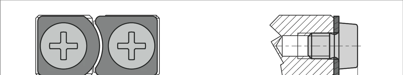
End Screws Type GA 1 to GA 12
Compatible with:
- Linear guideways R 1 to R 12
Installation method:
- For horizontal installation
- Not suitable for cage repositioning

| Size | GA 1 | GA 2 | GA 3 | GA 6 | GA 9 | GA 12 |
|---|---|---|---|---|---|---|
| a1 | 1.2 | 1.8 | 2 | 3 | 3 | 3 |
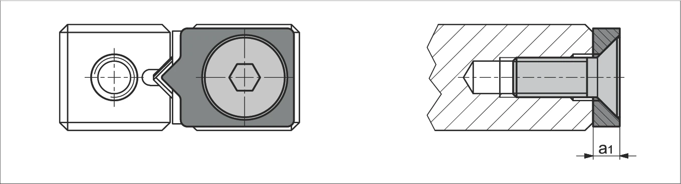
End Piece Type GB 1
Compatible with:
- Linear guideway R 1
Installation method:
- No restrictions
Scope of supply:
- Including end screw

| Size | GB 1 |
|---|---|
| a1 | 1.7 |
End Piece Type GB 2
Compatible with:
- Linear guideway R 2
Installation method:
- No restrictions
Scope of supply:
- Including end screw
| Size | GB 2 |
|---|---|
| a1 | 2 |
End Piece Type GB 3 to 12
Compatible with:
- Linear guideways R 3 to R 12
Installation method:
- No restrictions
Scope of supply:
- Including end screw

| Size | GB 3 | GB 6 | GB 9 | GB 12 |
|---|---|---|---|---|
| a1 | 2 | 3 | 4 | 5 |
End Piece Type GC 3 to GC 12
Compatible with:
- Linear guideways R 3 to R 12
Installation method:
- For overtravel cage
Scope of supply:
- Including end screw
| Size | GC 3 | GC 6 | GC 9 | GC 12 |
|---|---|---|---|---|
| a1 | 2 | 3 | 4 | 5 |
End Piece Type GC-A 3 to GC-A 12 (with scraper)
Compatible with:
- Linear guideways R 3 to R 12
Design:
- With felt scraper
Installation method:
- No restrictions
Scope of supply:
- Including end screw

| Size | GC-A 3 | GC-A 6 | GC-A 9 | GC-A 12 |
|---|---|---|---|---|
| a1 | 5 | 6 | 7 | 8 |
Fastening Screws with Thin Shaft Type GD 3 to GD 15
Features:
- Used to compensate for differences in hole spacing

| Type | Size | L | b | b1 | d1 | d2 | d3 | k | s | Max. tightening torque in Ncm* | Compatible with guideways of size | |
|---|---|---|---|---|---|---|---|---|---|---|---|---|
| (Situation 1) | (Situation 2) | |||||||||||
| GD | 3 | 12 | 5 | 7 | M3 | 5 | 2.3 | 3 | 2.5 | 94 | R 3 & RD 2 | R 2 & RD 1 |
| 4 | 16 | 7 | 9 | M4 | 6.5 | 3 | 4 | 3 | 221 | RD 3 | R 3 & RD 2 | |
| 6 | 20 | 8 | 12 | M5 | 8 | 3.9 | 5 | 4 | 463 | R 6 & RD 6 | RD 3 | |
| 9 | 30 | 12 | 18 | M6 | 8.5 | 4.6 | 6 | 5 | 762 | R 9 & RD 9 | R 6 & RD 6 | |
| 12 | 40 | 17 | 23 | M8 | 11.3 | 6.25 | 8 | 6 | 1838 | R 12 & RD 12 | R 9 & RD 9 | |
| 15 | 45 | 16 | 29 | M10 | 13.9 | 7.9 | 10 | 8 | 3674 | - | R 12 & RD 12 | |
* Tightening torque applies to materials with tensile strength > 360N/mm²