4.6.1 Accuracy Classes
SCHNEEBERGER offers four different accuracy classes for its MONORAIL guideways. They allow users to make precise and application-specific guideway selections based on design requirements.

Ultra-high precision, Super precision, High precision, Standard precision
The accuracy class determines the tolerance of the reference dimensions of the carriage relative to the guide rail, see figure below and section 4.6.2 - Accuracy - Dimensional tolerances, as well as the running accuracy of the carriage on the guide rail, see section 4.6.3 - Accuracy - Running accuracy.

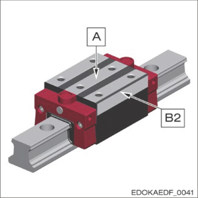
Reference measurement tolerance of carriage relative to guide rail
Legend
- 1 Carriage locating side
- 2 Guide rail locating side
- 3 Guide rail label side
- A System height
- B2 Distance between carriage locating side and guide rail locating side
Fields of Application
Accuracy Class: Ultra-High Precision
Application Examples:
- Measuring instruments
- Dressing devices
Accuracy Class: Super Precision
Application Examples:
- Measuring instruments
- Dressing devices
- CNC machine tools
- CNC machining centers
Accuracy Class: High Precision
Application Examples:
- CNC machine tools
- CNC machining centers
- Handling, robotics, auxiliary axes
Accuracy Class: Standard Precision
Application Examples:
- Handling, robotics, auxiliary axes
4.6.2 Dimensional Tolerances
System Dimensions A and B2
MONORAIL carriages and guide rails are manufactured independently with extremely high precision and are therefore completely interchangeable. This means that any carriage can be used on any guide rail of the same size without affecting the preload class, as the preload is determined by the rolling elements of the carriage. For dimensional differences of any carriage on any guide rail, the values in the "A/B2" column of the table below apply.

| Accuracy Class | A / B2 | ΔA / ΔB2 | ΔA Standard |
|---|---|---|---|
| G0 | ± 5 μm | 3 μm | 10 μm |
| G1 | ± 10 μm | 5 μm | 20 μm |
| G2 | ± 20 μm | 7 μm | 40 μm |
| G3 | ± 50 μm | 25 μm | 60 μm |
Dimensional Tolerance for Any Carriage on Any Guide Rail – A/B2
Measurement Position:
- Measured at the center of the carriage and any guide rail position
- Values apply only to guide rail lengths up to 1m

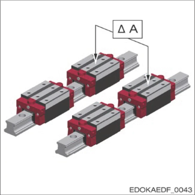
Maximum Dimensional Difference Between Carriages on a Guide Rail – ΔA/ΔB2
Measurement Position:
- Measured at the center of the carriage and the same guide rail position
- Values doubled for ball-type products and separately delivered products
Maximum Dimensional Difference of Carriages on Two or More Parallel Guide Rails, Standard – ΔA Standard
Measurement Position:
- Measured at the center of the carriage and the same guide rail position
Matched Carriages
All carriages in a set are matched to the production measurement standard and reground on their top and side locating surfaces. The main dimensions A and B2 are then measured on the master guide rail so that the carriages are matched to each other. Carriage matching can be provided in two qualities.
| Matched Carriages | Maximum Dimensional Difference of All Carriages Belonging to One Matched Set ΔA / ΔB2 | Implementation Code |
|---|---|---|
| Matching Quality 0 | 3 µm | SLWGP0 |
| Matching Quality 1 | 5 µm | SLWGP1 |
Matched Guide Rails
For "matched guide rails", suitable guide rails with similar running characteristics are sought from existing data. The criterion for the selection process is the maximum difference during running over the guide rail length, the so-called matching tolerance.
All boundaries of the running protocols are within this tolerance of the matched guide rails. Guide rail matching can be provided in four qualities.
| Guide Rail Matching | Matching Tolerance | Implementation Code |
|---|---|---|
| Matching Quality 0 | 5 µm | SLSGP0 |
| Matching Quality 1 | 10 µm | SLSGP1 |
| Matching Quality 2 | 15 µm | SLSGP2 |
| Matching Quality 3 | 20 µm | SLSGP3 |
Limited Tolerance of ΔA
For carriages assembled close together on the same guide rail or adjacent guide rails, limited tolerance of ΔA applies. When using a very rigid connecting structure to prevent reduced service life, the following conditions apply:

L = Carriage length
Lb = Distance between two carriages
ΔA = Dimensional deviation of system height
Note: Limited tolerance for carriages assembled close together on one guide rail
Dimensions of Guide Rails and Carriages
Guide Rail Width B1

Dimensions of Guide Rails and Carriages
Tolerance:
- Standard: ± 0.05 mm
Guide Rail Height J1
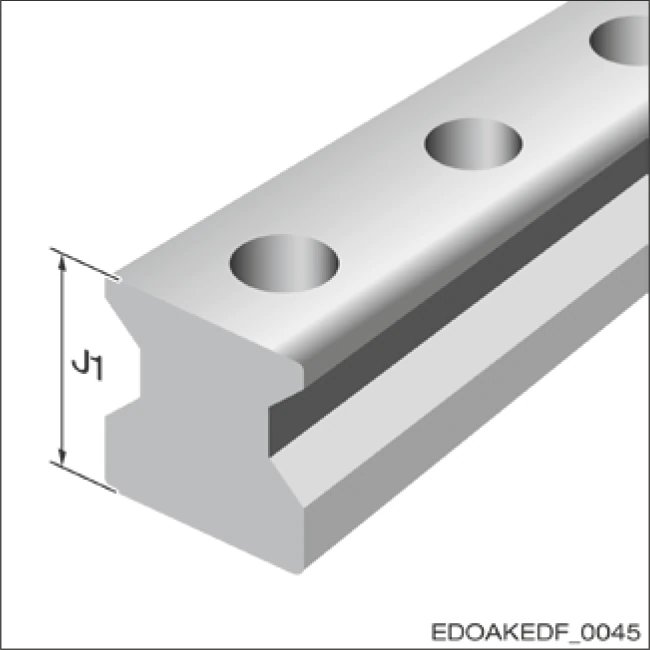
Tolerance:
- Standard/MAC/BAC: ± 0.05 mm
Carriage Width B

Standard Locating Surface Tolerance:
- MR: 0/-0.3 mm
- BM: 0/-0.4 mm

Double Locating Surface Tolerance:
- MR: -0.35/-0.25 mm
- BM: -0.35/-0.25 mm
4.6.3 Running Accuracy
Running accuracy describes the vertical and horizontal parallelism deviation of the carriage as it moves along the guide rail. It can exhibit a linear or undulating curve within the tolerance range (vertical XTZ and horizontal XTY). The tolerance class relative to the carriage center can be determined according to the following diagram, based on guide rail length and accuracy class.
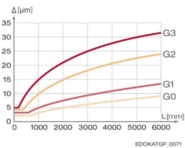
Reading example: For a guide rail length L3 = 2000 mm, the permissible tolerance for accuracy class G2 is 0.015 mm.