6.4.1 Arrangement of Measuring System and Reading Head
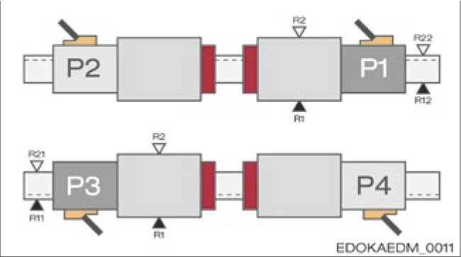
Reading Head Position and Positioning Side
The AMS reading head can be configured in four positions on the carriage. This supports flexible adaptation of the measuring system to structural design requirements.
Configuration requires the following steps:
- Determine the positioning side of the guide rail
- Determine the side of the optical scale
- All combinations are possible here. The respective designations are as follows:


- Determine the positioning side of the carriage relative to the guide rail
- Carriage positioning side:


- The reading head position can be determined from the previous steps and the need to position the reading head on the optical scale side.
- Housing position:
- No additional installation space or additional guide rail length is required to accommodate the housing and reading head
- The reading head is in a protected position between the carriages
- Generally the reading head is easily accessible for maintenance
Housing position
Arrangement of Measuring System
SCHNEEBERGER recommends positioning the reading head between carriages on the outside of the guide rail. This has the following advantages:

Fig. 6.xx - Reading head position with multiple carriages
In addition, the following recommendations should be considered depending on the installation orientation of the axis.
Horizontal Axis
Guide rails are placed horizontally next to each other, vertically or rotated 180°. The general recommendation to configure the reading head between carriages applies here. As long as the machine slide cover covers the guide rail and reading head area, and the machine setup prevents dirt or chip accumulation from depositing next to the guide rail, the reading head is well protected in any case. Additional protective measures are required when used in dirty working environments and when using coolants.
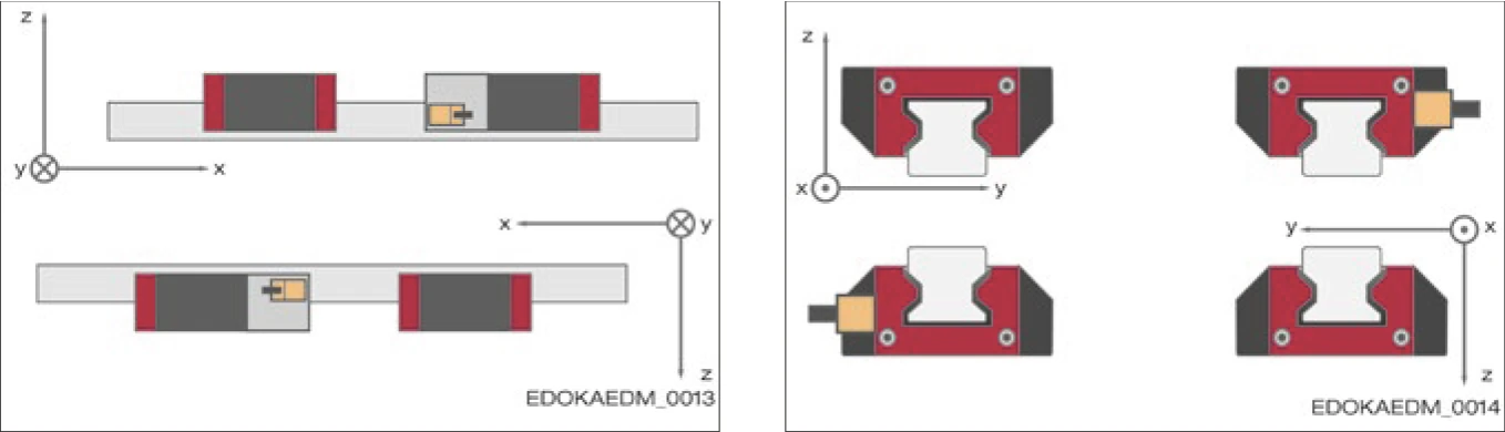
Fig. 6.xx - Reading head configuration for horizontal axis
Vertical Axis
The optimal position is suspended below the upper carriage as shown. Falling dirt particles and chips cannot deposit on the reading head. Lubricant supply is guaranteed by the lubrication connection on the upper carriage.

Fig. 6.xx - Reading head configuration for vertical axis
Horizontal Axis with Wall-Mounted Assembly
Guide rails are arranged one above the other and rotated 90°. The optimal position of the reading head, depending on axis accessibility, is on the underside of the bottom guide rail (as long as no chip dirt accumulates in this area), or on the underside of the top guide rail. This recommendation also applies to inclined bed axes, such as axes mounted rotated about the longitudinal axis.

Fig. 6.xx - Reading head configuration for wall-mounted horizontal axis; rotated 90° about longitudinal axis or inclined mounting, e.g., 45° inclination about longitudinal axis
For more information on guide rail configuration, installation orientation, and lubrication, please refer to Section 4.8 - Guide Rail Configuration and Section 4.9 - Guide Rail System Installation Methods.