MR Size 25 Technical Specifications
Medium-load applications in compact spaces
Rail Types MR S 25
| MR S 25-N | MR S 25-ND | MR S 25-NU | MR S 25-C | MR S 25-CD |
|---|---|---|---|---|
 | 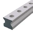 | 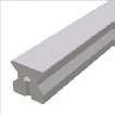 |  |  |
| Standard Top mounting | Standard, through-hardened Through-hardened | Bottom threaded hole Bottom mounting | Cover strip type For cover strip | Through-hardened cover strip Through-hardened |
Rail Dimensional Drawing MR S 25

Rail Specifications MR S 25
| Parameter | MR S 25-N | MR S 25-ND | MR S 25-NU | MR S 25-C | MR S 25-CD |
|---|---|---|---|---|---|
| Rail Width B1 (mm) | 23 | 23 | 23 | 23 | 23 |
| Rail Height J1 (mm) | 24.5 | 24.5 | 24.5 | 24.5 | 24.5 |
| Max. Single Length L3 (mm) | 6000 | 1500 | 6000 | 3000 | 1500 |
| Hole Pitch L4 (mm) | 30 | 30 | 30 | 30 | 30 |
| First/Last Hole Position L5/L10 (mm) | 13.5 | 13.5 | 13.5 | 13.5 | 13.5 |
| Weight per Unit (kg/m) | 3.4 | 3.4 | 3.8 | 3.3 | 3.3 |
Model Designations
- N = Standard (top mounting)
- ND = Standard, through-hardened
- NU = Bottom threaded hole (bottom mounting)
- C = Cover strip type
- CD = Through-hardened cover strip type
Carriage Types MR W 25
| MR W 25-A | MR W 25-B | MR W 25-C | MR W 25-D | MR W 25-E | MR W 25-F | MR W 25-G |
|---|---|---|---|---|---|---|
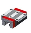 | 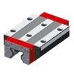 | 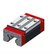 |  | 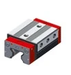 |  |  |
| Standard Standard | Standard long Standard long | High/flat High/flat | High/flat long High/flat long | Side fixing Side fixing | Flat Flat | Flat long Flat long |
Carriage Dimensional Drawing MR W 25

Carriage Specifications MR W 25
| Parameter | MR W 25-A | MR W 25-B | MR W 25-C | MR W 25-D | MR W 25-E | MR W 25-F | MR W 25-G |
|---|---|---|---|---|---|---|---|
| System Height A (mm) | 36 | 36 | 40 | 40 | 40 | 36 | 36 |
| Carriage Width B (mm) | 70 | 70 | 48 | 48 | 57 | 48 | 48 |
| Reference Distance B2 (mm) | 23.5 | 23.5 | 12.5 | 12.5 | 17 | 12.5 | 12.5 |
| Carriage Height J (mm) | 29.5 | 29.5 | 33.5 | 33.5 | 33.5 | 29.5 | 29.5 |
| Carriage Length L (mm) | 88 | 110 | 88 | 110 | 88 | 88 | 110 |
| Transverse Wiper Distance La (mm) | 83 | 106 | 83 | 106 | 83 | 83 | 106 |
| Outer Hole Pitch L1 (mm) | 45 | 45 | 35 | 50 | 35 | 35 | 50 |
| Inner Hole Pitch L2 (mm) | 40 | 40 | — | — | 35 | — | — |
| Steel Body Length L6 (mm) | 60 | 79.4 | 57 | 79.4 | 57 | 57 | 79.4 |
| Side Hole Pitch N (mm) | 57 | 57 | 35 | 35 | — | 35 | 35 |
| Reference Height O (mm) | 7.5 | 7.5 | 7.5 | 7.5 | 15 | 7.5 | 7.5 |
| Carriage Weight (kg) | 0.7 | 0.9 | 0.6 | 0.7 | 0.7 | 0.5 | 0.6 |
Rigidity Curves and Load Rating Diagrams

Load Ratings
| Carriage Type | C₀ Static Load (N) | C₁₀₀ Dynamic Load (N) | M₀Q Static Cross Moment (Nm) | M₀L Static Long. Moment (Nm) | MQ Dynamic Cross Moment (Nm) | ML Dynamic Long. Moment (Nm) |
|---|---|---|---|---|---|---|
| A / C / E / F | 49,800 | 27,700 | 733 | 476 | 408 | 264 |
| B / D / G | 70,300 | 39,100 | 1,035 | 936 | 575 | 520 |
Load Rating Definitions
- C₀ = Static load capacity - Maximum allowable load causing permanent deformation
- C₁₀₀ = Dynamic load capacity - Load for 100km travel life
- M₀Q / MQ = Cross moment - Rotation around travel axis
- M₀L / ML = Longitudinal moment - Rotation around vertical axis
Available Options
Accuracy Classes
| Accuracy Class | Carriage & Rail Tolerance A/B2 | Max. Deviation Paired Carriages ΔA/ΔB2 | Max. Deviation Standard Carriages |
|---|---|---|---|
| G0 Highly accurate | ± 5 µm | 3 µm | 10 µm |
| G1 Very accurate | ± 10 µm | 5 µm | 20 µm |
| G2 Accurate | ± 20 µm | 7 µm | 40 µm |
| G3 Standard | ± 30 µm | 25 µm | 60 µm |
Preload Classes
| Preload Class | Preload Force (% of C₀) | Applications |
|---|---|---|
| V0 Very light preload | 0-2% | Very low friction, uniform load, minimum vibration |
| V1 Light preload | 3% | Low friction, uniform load, slight vibration |
| V2 Medium preload | 8% | High rigidity, moderate varying loads and vibration |
| V3 High preload | 13% | Maximum rigidity, impact loads, severe varying loads |
Lubrication Port Positions


| Code | Position | Description |
|---|---|---|
| S10 | Left center | Left center of front plate |
| S11 | Top center | Top center of carriage |
| S12 | Top left | Top left of carriage |
| S13 | Lower left side | Lower left side of carriage |
| S20 | Right center | Right center of front plate |
| S21 | Rear center | Center of rear plate |
| S22 | Top right | Top right of carriage |
| S23 | Lower right side | Lower right side of carriage |
| S32 | Upper left side | Upper left side of carriage |
| S42 | Upper right side | Upper right side of carriage |
| S98 | Special position | As per customer specification |
| S99 | Special position | As per customer specification |
Lubrication as Delivered
| Code | Type | Description | Applications |
|---|---|---|---|
| LN | Oil protection | Light oiling | Applications with continuous oil supply after installation |
| LG | Grease protection | Thin grease layer | Applications with continuous grease supply after installation |
| LV | Full greasing | Complete grease filling | Applications with manual lubrication |
Surface Treatment (Coating)
| Code | Type | Features |
|---|---|---|
| — | Standard (uncoated) | Standard steel surface |
| CN | Hard chromium | Excellent corrosion protection, high wear resistance, good emergency running properties |
Reference Side Position
R1 - Reference at bottom R2 - Reference on top
Order Code Examples
Rail Order Code
MR S 25-N-G1-KC-R1-600-13.5-13.5-CN
- MR S 25 = MONORAIL Rail Size 25
- N = Standard type
- G1 = High precision
- KC = Countersunk holes
- R1 = Reference at bottom
- 600 = Rail length 600mm
- 13.5-13.5 = First/last hole positions
- CN = Hard chrome plating
Carriage Order Code
MR W 25-A-G1-V2-R1-CN-S11-LV
- MR W 25 = MONORAIL Carriage Size 25
- A = Standard type
- G1 = High precision
- V2 = Standard preload (4% C₀)
- R1 = Reference at bottom
- CN = Hard chrome plating
- S11 = Lubrication port at top center
- LV = Full grease fill as delivered