6.6.1 Definition
Shielding, in a broad sense, refers to protecting electronic equipment from electromagnetic interference. This can affect the equipment due to electromagnetic radiation, or it can be conductor-based, in which case transmission from one conductor to another susceptible to interference may occur due to capacitive or inductive coupling. Since the frequency range of electromagnetic interference in industrial environments is very wide, from about 10 kHz for contactors, switching regulators, etc., to 3 GHz for mobile phones, and the different mechanisms of interference transmission largely depend on frequency, it is difficult to predict which transmission path dominates in the respective application and which shielding measures will be most effective.
6.6.2 Types of Shielding
Most shielding measures use the concept of a Faraday cage or interference release, mainly referring to the general reference potential "ground" or "protective ground line", in which case both methods are usually combined with each other. The principle of the Faraday cage is based on the fact that the interior of a closed conductive object is field-free. Cable shielding is an example of a Faraday cage where a "closed state" of 85% or higher is achieved, in other words coverage. Interference currents flowing in the cable shield, i.e., voltages and currents caused by external electromagnetic radiation, need to be released as effectively as possible to the reference potential. In the case of AC voltage, frequency-dependent complex resistance (impedance) occurs, which causes interference voltage drops, especially at the junction points of different equipment components, such as cable shields, plugs, housings, covers, ground terminals, etc. Lower DC resistance does not indicate the quality (impedance) of the connection in terms of high-frequency interference fields. Short longitudinal dimensions, large cross-sections, large-area connections of two parts, and large distances from interference sources are all helpful. On the other hand, long thin ground wires are more or less ineffective.
The emitted interference or susceptibility to interference of electrical and electronic systems is regulated by various international standards, and there are numerous standardized test procedures. The SCHNEEBERGER AMS system has been tested and passed such tests according to standards EN 55011, EN 61000-4-2, EN 61000-4-3, EN 61000-4-4, EN 61000-4-5, EN 61000-4-6, and ENV 50204.
6.6.3 Shielding for the SCHNEEBERGER Distance Measuring System
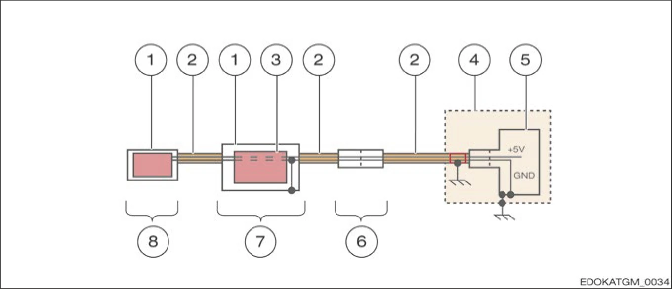
Figure 6.xx - SCHNEEBERGER Shielding Design
The housing with cable shielding forms a closed Faraday cage. The cable shield is connected to the connector housing. To ground the measuring system, the outer shield of the cable must be connected to ground in the switch cabinet, so interference currents can be released in this way. In the switch cabinet or controller, 0 V = GND is connected to ground (protective ground line). By using EMC-compliant cable glands, the transition from cable shield to housing can also be achieved at low impedance. Otherwise, in the electronic housing, 0V is connected to the shield, which means interference can also be effectively transferred to the power cable.