MR Size 65 Technical Specifications
Ultra-high load and moment capacity
Rail Types MR S 65
| MR S 65-N | MR S 65-NU | MR S 65-C |
|---|---|---|
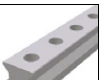 |  |  |
| Standard Top mounting | Bottom tapped holes Bottom mounting | Cover strip type For cover strip |
Rail Dimensional Drawing MR S 65

Rail Specifications MR S 65
| Parameter | MR S 65-N | MR S 65-NU | MR S 65-C |
|---|---|---|---|
| Rail Width B1 (mm) | 63 | 63 | 63 |
| Rail Height J1 (mm) | 58 | 58 | 58 |
| Max Single Length L3 (mm) | 6000 | 6000 | 6000 |
| Fixing Hole Pitch L4 (mm) | 75 | 75 | 75 |
| First/Last Hole Position L5/L10 (mm) | 36 | 36 | 36 |
| Unit Weight (kg/m) | 22.8 | 24.5 | 22.5 |
Model Description
- N = Standard (top mounting)
- NU = Bottom tapped holes (bottom mounting)
- C = Cover strip type
Carriage Types MR W 65
| MR W 65-A | MR W 65-B | MR W 65-C | MR W 65-D | MR W 65-P |
|---|---|---|---|---|
 |  |  |  | 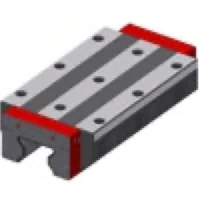 |
| Standard Standard | Standard long Standard long | High/flat High/flat | High/flat long High/flat long | Standard extra long Standard extra long |
Size 65 Exclusive Type
Type P (Standard extra long) is a carriage type exclusive to Size 65, providing additional load capacity and stability.
Carriage Dimensional Drawing MR W 65

Carriage Specifications MR W 65
| Parameter | MR W 65-A | MR W 65-B | MR W 65-C | MR W 65-D | MR W 65-P |
|---|---|---|---|---|---|
| System Height A (mm) | 90 | 90 | 90 | 90 | 90 |
| Carriage Width B (mm) | 170 | 170 | 126 | 126 | 170 |
| Reference Surface Distance B2 (mm) | 53.5 | 53.5 | 31.5 | 31.5 | 53.5 |
| Carriage Height J (mm) | 76.2 | 76.2 | 76.2 | 76.2 | 76.2 |
| Carriage Length L (mm) | 207 | 260 | 207 | 260 | 331 |
| Outer Fixing Hole Pitch L1 (mm) | 110 | 110 | 70 | 120 | 200 |
| Inner Fixing Hole Pitch L2 (mm) | 82 | 82 | — | — | — |
| Steel Body Length L6 (mm) | 148.5 | 201 | 148.5 | 201 | 272 |
| Side Fixing Hole Pitch N (mm) | 142 | 142 | 76 | 76 | 142 |
| Reference Surface Height O (mm) | 15 | 15 | 15 | 15 | 15 |
| Carriage Weight (kg) | 10.2 | 13.5 | 8.0 | 10.4 | 20.3 |
Rigidity Curves and Load Rating Diagrams

Load Ratings
| Carriage Type | C₀ Static Load (N) | C₁₀₀ Dynamic Load (N) | M₀Q Static Cross Moment (Nm) | M₀L Static Long. Moment (Nm) | MQ Dynamic Cross Moment (Nm) | ML Dynamic Long. Moment (Nm) |
|---|---|---|---|---|---|---|
| A / C | 419,000 | 232,000 | 16,446 | 10,754 | 9,154 | 5,954 |
| B / D | 530,000 | 295,000 | 20,912 | 17,930 | 11,640 | 9,980 |
| P | 748,200 | 366,000 | 29,479 | 32,300 | 14,429 | 15,800 |
Available Options
Accuracy Classes
| Accuracy Class | Carriage & Rail Tolerance A/B2 | Matched Carriage Max Difference ΔA/ΔB2 | Standard Carriage Max Difference |
|---|---|---|---|
| G0 Highly accurate | ± 5 µm | 3 µm | 10 µm |
| G1 Very accurate | ± 10 µm | 5 µm | 20 µm |
| G2 Accurate | ± 20 µm | 7 µm | 40 µm |
| G3 Standard | ± 30 µm | 25 µm | 60 µm |
Preload Classes
| Preload Class | Preload Force (% of C₀) | Application |
|---|---|---|
| V0 Very light preload | 0-2% | Very low friction, uniform load, minimum vibration |
| V1 Light preload | 3% | Low friction, uniform load, slight vibration |
| V2 Medium preload | 8% | High rigidity, moderate varying loads and vibration |
| V3 High preload | 13% | Maximum rigidity, impact loads, severe varying loads |
Coating
| Code | Type | Features |
|---|---|---|
| — | Standard (no coating) | Standard steel surface |
| CN | Hard chromium | Excellent corrosion resistance, high wear resistance, good emergency running properties |
Reference Side
R1 - Reference at bottom R2 - Reference on top
Order Code Examples
Rail Order Code
MR S 65-N-G1-KC-R1-2000-36-36-CN
- MR S 65 = MONORAIL Rail Size 65
- N = Standard type
- G1 = Very accurate
- KC = Fixing holes with countersink
- R1 = Reference at bottom
- 2000 = Rail length 2000mm
- 36-36 = First/last hole positions
- CN = Hard chromium coating
Carriage Order Code
MR W 65-P-G1-V2-R1-CN-S11-LV
- MR W 65 = MONORAIL Carriage Size 65
- P = Extra long carriage type
- G1 = Very accurate
- V2 = Medium preload (8% C₀)
- R1 = Reference at bottom
- CN = Hard chromium coating
- S11 = Lubrication hole position top center
- LV = Full greasing as delivered