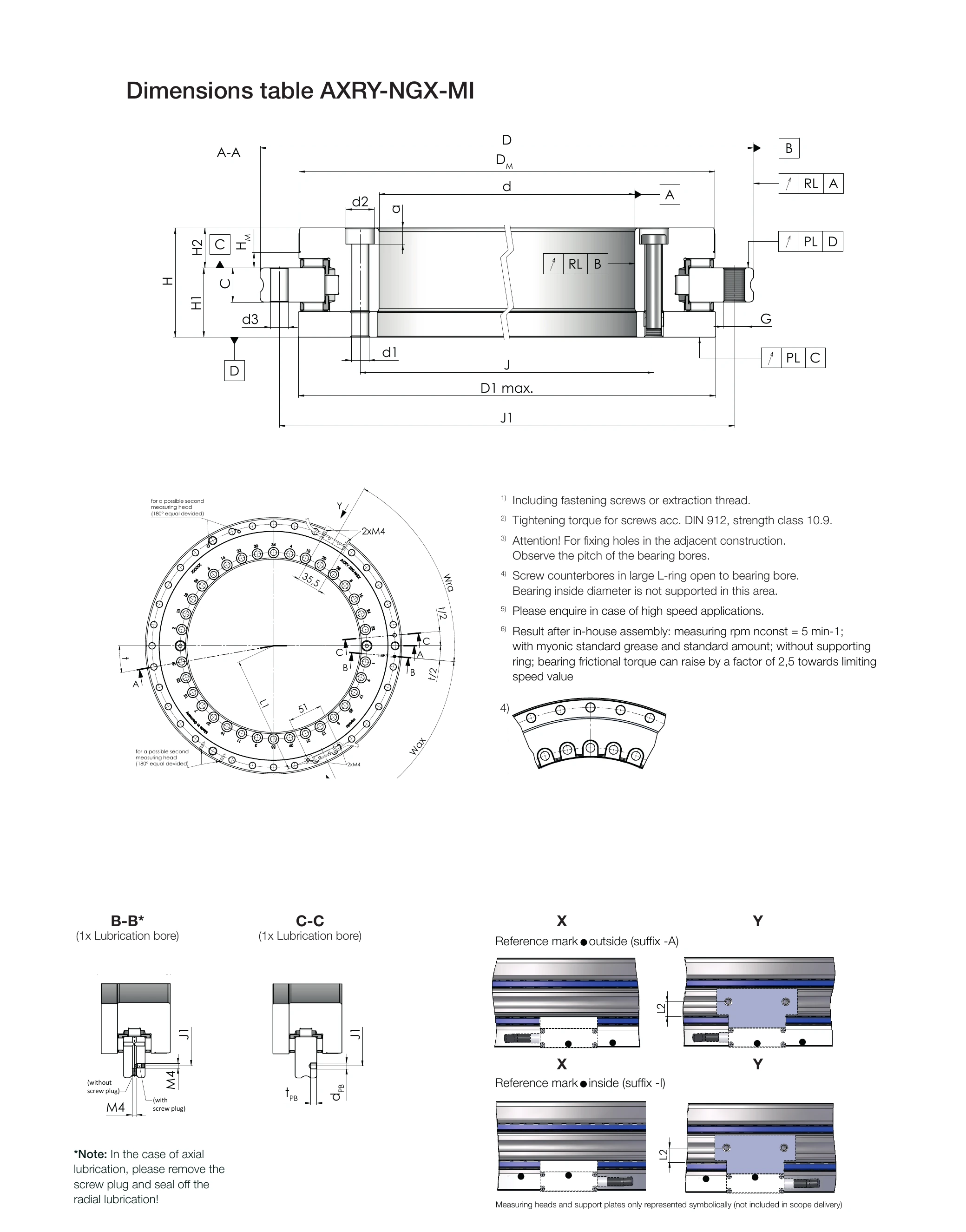
Dimension Diagram
(Click the image to enlarge)
The AXRY-NGX-MI series is based on the NGX bearing, with an incremental angle measuring ring integrated into the outer ring. The measuring head is not included in the bearing scope of delivery and must be ordered separately. Applicable shaft journal diameters: 180 to 650 mm (8 standard sizes).
Main Dimensions
- d: Bore diameter (shaft journal diameter)
- D: Outside diameter
- H: Height
- H1: Connection dimension H1 (table side)
- H2: Connection dimension H2 (shaft side)
- m: Weight (kg); "-" indicates not published in the datasheet
| Model | d [mm] | D [mm] | H [mm] | H1 [mm] | H2 [mm] | m [kg] |
|---|---|---|---|---|---|---|
| AXRY 180-NGX-MI | 180 | 280 | 50 | 29 | 21 | - |
| AXRY 200-NGX-MI | 200 | 300 | 51 | 30 | 21 | 10.5 |
| AXRY 260-NGX-MI | 260 | 385 | 57.5 | 36.5 | 21 | 18.4 |
| AXRY 325-NGX-MI | 325 | 450 | 61 | 40 | 21 | 25.2 |
| AXRY 395-NGX-MI | 395 | 525 | 65 | 42.5 | 22.5 | 32.2 |
| AXRY 460-NGX-MI | 460 | 600 | 70 | 46 | 24 | 44.8 |
| AXRY 580-NGX-MI | 580 | 750 | 90 | 60 | 30 | - |
| AXRY 650-NGX-MI | 650 | 870 | 122 | 78 | 44 | - |
AXRY 150-NGX-MI has no official datasheet for confirmation; its main dimensions are not listed in this table. See the distance plate section below for its distance plate dimensions.
Load Ratings & Speed
- Ca: Dynamic load rating, axial
- C0a: Static load rating, axial
- Cr: Dynamic load rating, radial
- C0r: Static load rating, radial
- nG: Limiting speed; for long-term continuous operation, please contact sales@eb-system.com
- MR: Bearing friction torque (reference value)
| Model | Ca [kN] | C0a [kN] | Cr [kN] | C0r [kN] | nG [rpm] | MR [Nm] |
|---|---|---|---|---|---|---|
| AXRY 180-NGX-MI | 139.3 | 755.0 | 99.4 | 200.3 | 600 | 5 |
| AXRY 200-NGX-MI | 151.0 | 871.2 | 122.1 | 273.9 | 450 | 6 |
| AXRY 260-NGX-MI | 220.1 | 1520.6 | 138.3 | 349.0 | 300 | 9 |
| AXRY 325-NGX-MI | 249.3 | 1900.8 | 181.7 | 531.4 | 200 | 13 |
| AXRY 395-NGX-MI | 275.7 | 2281.0 | 199.2 | 633.8 | 200 | 19 |
| AXRY 460-NGX-MI | 299.5 | 2661.1 | 232.5 | 739.0 | 150 | 25 |
| AXRY 580-NGX-MI | 584.6 | 4457.4 | 284.5 | 867.2 | 80 | 60 |
| AXRY 650-NGX-MI | 1010.7 | 7682.4 | 459.6 | 1317.1 | 70 | 70 |
Rigidity
- caL: Axial rigidity of bearing position (kN/µm)
- crL: Radial rigidity of bearing position (kN/µm)
- ckL: Tilting rigidity of bearing position (kNm/mrad)
| Model | caL [kN/µm] | crL [kN/µm] | ckL [kNm/mrad] |
|---|---|---|---|
| AXRY 180-NGX-MI | 9.0 | 3.2 | 57.2 |
| AXRY 200-NGX-MI | 8.9 | 4.1 | 69.7 |
| AXRY 260-NGX-MI | 12.7 | 5.1 | 159.4 |
| AXRY 325-NGX-MI | 15.4 | 7.2 | 275.8 |
| AXRY 395-NGX-MI | 18.3 | 8.4 | 459.4 |
| AXRY 460-NGX-MI | 21.9 | 8.6 | 736.9 |
| AXRY 580-NGX-MI | 22.9 | 8.8 | 1207 |
| AXRY 650-NGX-MI | 27.1 | 9.7 | 1880.1 |
Runout
- PL: Axial runout (Plan Lauf)
- RL: Radial runout (Radial Lauf)
- Standard: Standard accuracy grade
- Restricted (-PRR50): Restricted accuracy grade, ordered with the suffix code -PRR50
| Model | Standard PL & RL [µm] | Restricted PL & RL (-PRR50) [µm] |
|---|---|---|
| AXRY 180-NGX-MI | 4 | 2 |
| AXRY 200-NGX-MI | 4 | 2 |
| AXRY 260-NGX-MI | 6 | 3 |
| AXRY 325-NGX-MI | 6 | 3 |
| AXRY 395-NGX-MI | 6 | 3 |
| AXRY 460-NGX-MI | 6 | 3 |
| AXRY 580-NGX-MI | 10 | 5 |
| AXRY 650-NGX-MI | 10 | 5 |
Measurement Ring Data
The following data are taken from the SPECIFIC MEASUREMENT BEARING DATA section of each model's datasheet. The measuring head and bracket are not included in the scope of delivery; illustrations are for reference only.
- DM: Outside diameter of measuring ring (mm)
- HM: Distance from measuring ring to outer ring (mm)
| Model | DM [mm] | HM [mm] |
|---|---|---|
| AXRY 180-NGX-MI | 245.0 | 6 |
| AXRY 200-NGX-MI | 274.2 | 6 |
| AXRY 260-NGX-MI | 344.3 | 8 |
| AXRY 325-NGX-MI | 415.0 | 8 |
| AXRY 395-NGX-MI | 484.4 | 8 |
| AXRY 460-NGX-MI | 558.2 | 10 |
| AXRY 580-NGX-MI | 700.9 | 15 |
| AXRY 650-NGX-MI | 796.4 | 21 |
Incremental Measuring Head Distance Plate Recommendation
Recommendation Distance Plates for Incremental Measuring Heads
If you want to mount the incremental measuring head directly onto the bearing outer ring, a distance plate is required. To enable the measuring head to measure at the correct position, the distance plate must be used to adjust the two distances DP-L and DP-H.

DP-H: Distance plate height (vertical direction) | DP-L: Distance plate length offset (horizontal direction)
| Bearing Model | DP-H [mm] | DP-L [mm] |
|---|---|---|
| AXRY 150 | 5 | 4.56 |
| AXRY 180 | 5 | 4.62 |
| AXRY 200 | 5 | 4.60 |
| AXRY 260 | 7 | 4.07 |
| AXRY 325 | 7 | 4.10 |
| AXRY 395 | 7 | 2.29 |
| AXRY 460 | 9 | 2.65 |
| AXRY 580 | 14 | 4.53 |
| AXRY 650 | 20 | 2.63 |
Distance plate values source: product-myonic.com/masstabelle-axry-ngx-mi (verified 2026-06-27).
The AXRY 150 distance plate values have been confirmed on the official website; the AXRY 150-NGX-MI bearing main specifications (d/D/H/load) await confirmation from an official datasheet.
The distance plate must be provided by the customer.
Installation Notes
- The bearing outer ring is already provided with M4 threads at a spacing of 51 mm (M4 Gewinde in einem Abstand von 51 mm bereits vorhanden)
- The distance plate secures the measuring head via M3 threads at a spacing of 16 mm (M3 Gewinde in Abstand von 16 mm)
- The distance plate must be provided by the customer
- The measuring head and bracket are not included in the bearing scope of delivery; illustrations are for reference only
Notes
- The data on this page are taken directly from the official myonic datasheets (each model, 2024-02-06 revision); the datasheet is the final authority
- There is currently no official datasheet to confirm the main specifications of the AXRY 150-NGX-MI; please contact sales@eb-system.com for selection assistance
- nG (limiting speed) applies to general applications; for long-term continuous high-speed operation, please contact sales@eb-system.com separately
- MR (friction torque) is a reference value; the actual value depends on the preload grade and lubrication conditions
- The measuring head and bracket are not included in the AXRY-NGX-MI scope of delivery; they must be ordered separately and the measuring head specifications obtained accordingly
- For special configurations or customized designs, please email sales@eb-system.com