BM Size 35 Technical Specifications
Balancing High Load and High Speed
Rail Types BM S 35
| BM S 35-N | BM S 35-NU | BM S 35-C |
|---|---|---|
 |  |  |
| Standard Standard | Tapped Holes at Bottom Tapped holes at bottom | Cover Strip Cover strip |
Rail Dimensions BM S 35

Rail Specifications BM S 35
| Parameter | BM S 35-N | BM S 35-NU | BM S 35-C |
|---|---|---|---|
| Rail Width B1 (mm) | 34 | 34 | 34 |
| Rail Height J1 (mm) | 29.5 | 29.5 | 29.5 |
| Max Single Piece Length L3 (mm) | 6000 | 6000 | 6000 |
| Mounting Hole Pitch L4 (mm) | 80 | 80 | 80 |
| First/Last Hole Position L5/L10 (mm) | 38.5 | 38.5 | 38.5 |
| Weight per Meter (kg/m) | 5.4 | 5.7 | 5.2 |
Carriage Types BM W 35
| BM W 35-A / B | BM W 35-C / D | BM W 35-E | BM W 35-F / G |
|---|---|---|---|
 | 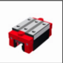 | 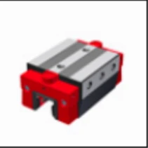 |  |
| Standard / Standard Long Standard / Standard long | Compact High / Compact High Long Compact high / long | Lateral Mounting Lateral fixation | Compact / Compact Long Compact / Compact long |
Carriage Dimensions BM W 35

Carriage Specifications BM W 35
| Parameter | BM W 35-A | BM W 35-B | BM W 35-C | BM W 35-D | BM W 35-F | BM W 35-G | BM W 35-H | BM W 35-J | BM W 35-K | BM W 35-L | BM W 35-M | BM W 35-N |
|---|---|---|---|---|---|---|---|---|---|---|---|---|
| System Height A (mm) | 48 | 48 | 55 | 55 | 55 | 55 | 48 | 48 | 44 | 44 | 44 | 48 |
| Carriage Width B (mm) | 100 | 100 | 70 | 70 | 70 | 70 | 100 | 100 | 70 | 70 | 55 | 70 |
| Reference Surface Distance B2 (mm) | 33 | 33 | 18 | 18 | 18 | 18 | 33 | 33 | 18 | 18 | 15 | 18 |
| Carriage Height J (mm) | 40.8 | 40.8 | 48.2 | 48.2 | 48.2 | 48.2 | 40.8 | 40.8 | 36.8 | 36.8 | 36.8 | 40.8 |
| Carriage Length L (mm) | 110.3 | 127.6 | 110.3 | 127.6 | 97.4 | 110.3 | 127.6 | 79.5 | 110.3 | 79.5 | 110.3 | 79.5 |
| Steel Body Length L6 (mm) | 78.3 | 95.6 | 76.1 | 95.6 | 63.2 | 76.1 | 95.6 | 47.5 | 78.1 | 47.5 | 78.3 | 47.5 |
| Lateral Mounting Hole Pitch N (mm) | 86 | 86 | 56 | 56 | 56 | 56 | 86 | 90 | 56 | 56 | 44 | 56 |
| Reference Surface Height O (mm) | 6.5 | 6.5 | 6.5 | 6.5 | 6.5 | 6.5 | 6.5 | 6.5 | 6.5 | 6.5 | 6.5 | 6.5 |
| Carriage Weight (kg) | 1.8 | 2.5 | 1.5 | 2.2 | 1.4 | 1.8 | 1.2 | 1.2 | 1.3 | 0.9 | 1.2 | 0.9 |
Rigidity Curve and Load Ratings
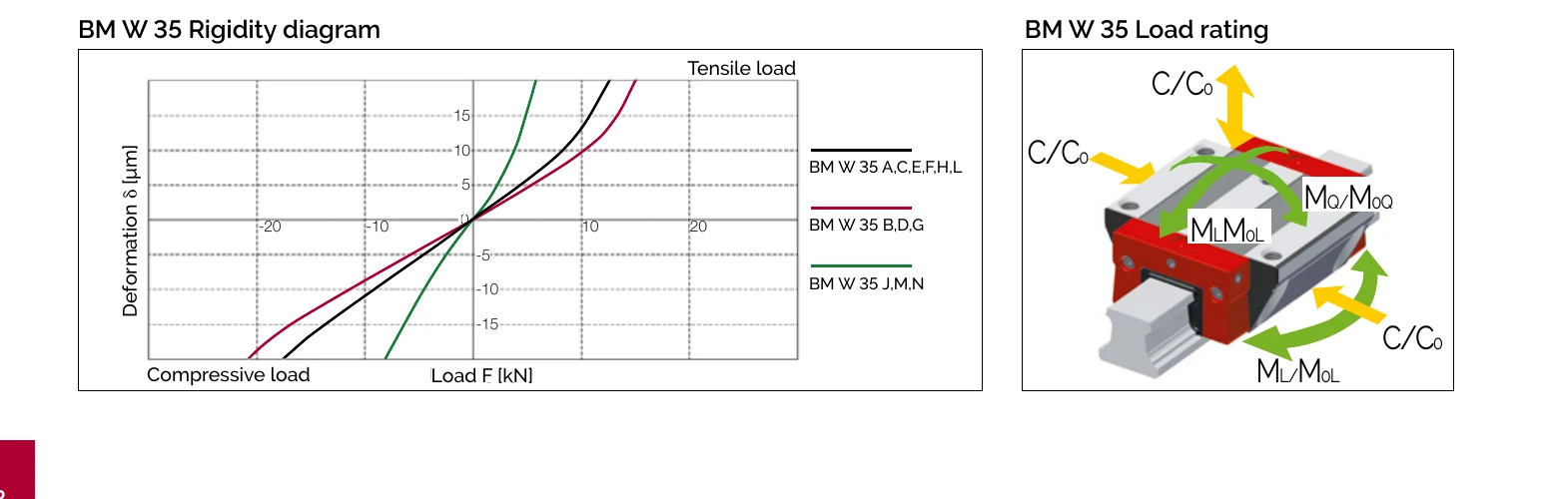
Load Ratings
| Carriage Type | C₀ Static Load (N) | C₁₀₀ Dynamic Load (N) | M₀Q Static Cross Moment (Nm) | M₀L Static Long. Moment (Nm) | MQ Dynamic Cross Moment (Nm) | ML Dynamic Long. Moment (Nm) |
|---|---|---|---|---|---|---|
| A / C / E / F / H / L | 84,400 | 38,700 | 1,566 | 1,252 | 718 | 574 |
| B / D / G | 110,300 | 46,700 | 2,048 | 2,104 | 867 | 891 |
| J / M / N | 37,700 | 25,800 | 717 | 240 | 492 | 172 |
Load Rating Definitions
- C₀ = Static load capacity
- C₁₀₀ = Dynamic load capacity - 100km travel life
- M₀Q / MQ = Cross moment (lateral)
- M₀L / ML = Longitudinal moment
Available Options
Accuracy Classes
| Accuracy Class | Carriage/Rail Tolerance A/B2 | Matched Carriage Max Deviation ΔA/ΔB2 | Standard Carriage Max Deviation |
|---|---|---|---|
| G0 Highly Accurate | ± 5 µm | 3 µm | 10 µm |
| G1 Very Accurate | ± 10 µm | 5 µm | 20 µm |
| G2 Accurate | ± 20 µm | 7 µm | 40 µm |
| G3 Standard | ± 30 µm | 25 µm | 60 µm |
Preload Classes
| Preload Class | Preload Force (% of C₀) | Application |
|---|---|---|
| V0 Extra Light Preload | 0-2% | Extremely low friction, uniform load, minimal vibration |
| V1 Light Preload | 3% | Low friction, uniform load, slight vibration |
| V2 Medium Preload | 8% | High rigidity, moderate variable load and vibration |
| V3 High Preload | 13% | Maximum rigidity, impact loads, highly variable loads |
Reference Side
R1 - Reference at Bottom R2 - Reference on Top
Order Code Examples
Rail Order Code
BM S 35-N-G1-KC-R1-500-38.5-38.5
- BM S 35 = MONORAIL Ball Profile Rail Size 35
- N = Standard (top mounting)
- G1 = Very Accurate
- KC = Countersunk mounting holes
- R1 = Reference at bottom
- 500 = Rail length 500mm
- 38.5-38.5 = First/last hole positions
Carriage Order Code
BM W 35-A-V1-S11-LV-CN
- BM W 35 = MONORAIL Ball Profile Carriage Size 35
- A = Standard carriage
- V1 = Light preload
- S11 = Lubrication port position (top center)
- LV = Full greasing
- CN = Hard chromium coating