Dimension Notation
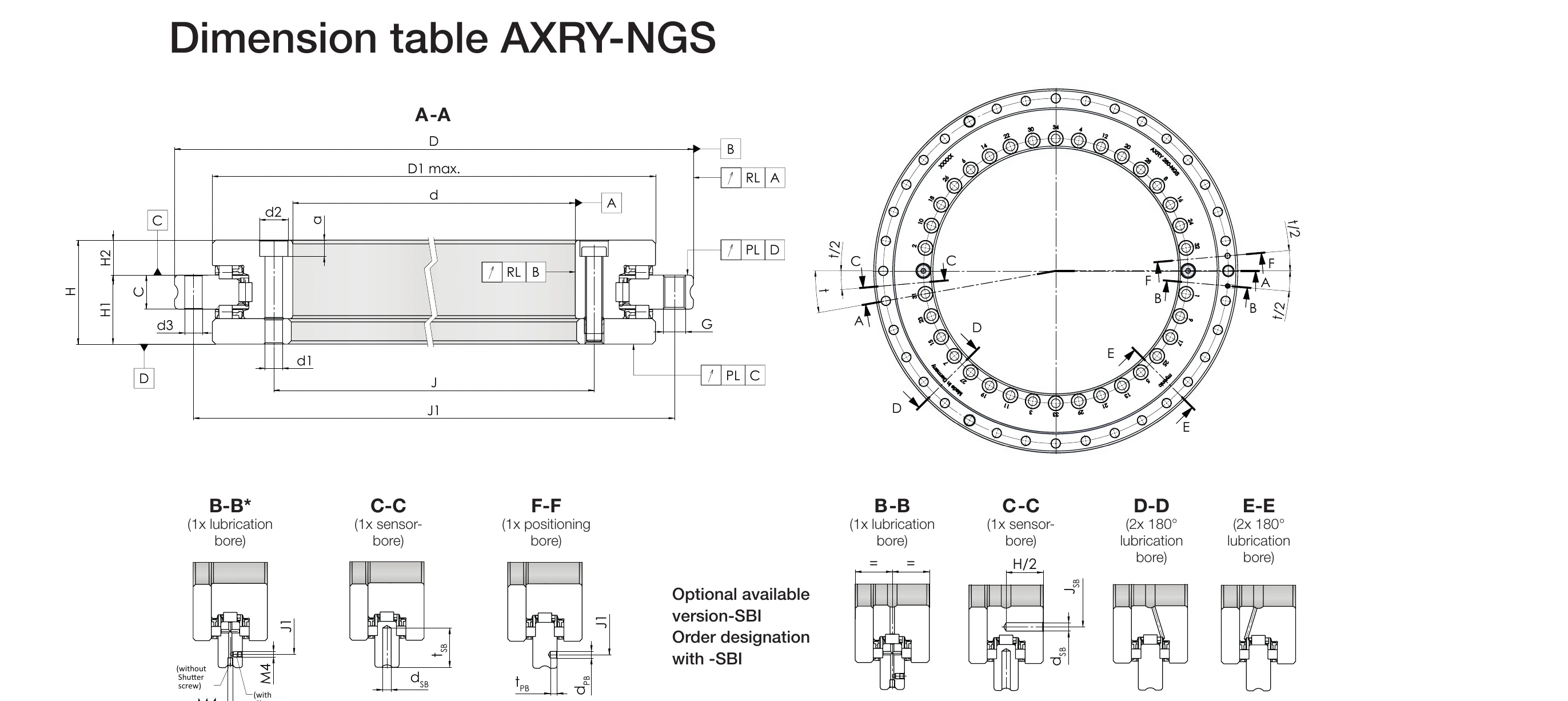
* For axial lubrication, remove the screw plug and seal the radial lubrication bore. Source: myonic official catalog EMO 2025.
Main Dimensions
Legend
- d: Bore diameter [mm]
- D: Outer diameter [mm]
- H: Overall height [mm]
- H1: Connection dimension H1 [mm]
- H2: Connection dimension H2 [mm]; ordering code -H2 for optional restricted tolerance
- m: Weight [kg]
| Model | d [mm] | D [mm] | H [mm] | H1 [mm] | H2 [mm] | Weight [kg] |
|---|---|---|---|---|---|---|
| AXRY 100-NGS | 100 | 185 | 38 | 25 | 13 | 3.5 |
| AXRY 120-NGS | 120 | 210 | 40 | 26 | 14 | 4.5 |
| AXRY 150-NGS | 150 | 240 | 40 | 26 | 14 | 5.2 |
| AXRY 180-NGS | 180 | 280 | 43 | 29 | 14 | 7.0 |
| AXRY 200-NGS | 200 | 300 | 45 | 30 | 15 | 9.0 |
| AXRY 260-NGS | 260 | 385 | 55 | 36.5 | 18.5 | 17.1 |
| AXRY 325-NGS | 325 | 450 | 60 | 40 | 20 | 23.9 |
| AXRY 395-NGS | 395 | 525 | 65 | 42.5 | 22.5 | 31.6 |
| AXRY 460-NGS | 460 | 600 | 70 | 46 | 24 | 42.4 |
| AXRY 580-NGS | 580 | 750 | 90 | 60 | 30 | 84.8 |
| AXRY 650-NGS | 650 | 870 | 122 | 78 | 44 | 162.3 |
The standard and restricted tolerances for H2 (ordering code -H2) apply to all models; see the dimension column of each model's datasheet.
Load Capacity and Rigidity
Legend
- Ca: Dynamic axial load rating [kN]
- C0a: Static axial load rating [kN]
- Cr: Dynamic radial load rating [kN]
- C0r: Static radial load rating [kN]
- Cal: Axial rigidity [kN/µm]
- Crl: Radial rigidity [kN/µm]
- Ckl: Tilting rigidity [kNm/mrad]
- nG: Limiting speed [min-1]; values in parentheses (*) are not yet verified (datasheet marked "not verified yet")
| Model | Ca [kN] | C0a [kN] | Cr [kN] | C0r [kN] | Cal [kN/µm] | Crl [kN/µm] | Ckl [kNm/mrad] | nG [min-1] |
|---|---|---|---|---|---|---|---|---|
| AXRY 100-NGS | 86.5 | 380.7 | 49.6 | 90.3 | 3.5 | 1.7 | 9.1 | (2500)* |
| AXRY 120-NGS | 100.4 | 484.7 | 40.1 | 82.8 | 4.1 | 1.9 | 14.2 | 2150 |
| AXRY 150-NGS | 105.5 | 543.8 | 60.2 | 130.8 | 4.8 | 2.4 | 23.6 | (1800)* |
| AXRY 180-NGS | 142.6 | 751.5 | 88.0 | 200.3 | 6.0 | 3.2 | 38.8 | (1750)* |
| AXRY 200-NGS | 159.2 | 901.8 | 93.5 | 226.2 | 6.6 | 3.5 | 53.1 | 1600 |
| AXRY 260-NGS | 178.7 | 1127.3 | 110.1 | 303.5 | 8.8 | 4.6 | 114.8 | 1200 |
| AXRY 325-NGS | 188 | 1277.6 | 115.6 | 345.4 | 10.3 | 5.2 | 193.4 | 1000 |
| AXRY 395-NGS | 212.5 | 1578.2 | 154.1 | 529.8 | 12.9 | 7.2 | 337.5 | 800 |
| AXRY 460-NGS | 190.9 | 1427.9 | 177.1 | 605.6 | 12.9 | 7.5 | 455.1 | 700 |
| AXRY 580-NGS | 484.7 | 3492.7 | 251.6 | 867.2 | 16.9 | 8.8 | 917.2 | 500 |
| AXRY 650-NGS | 816.3 | 5829.1 | 406.6 | 1317.1 | 20.3 | 9.8 | 1451.2 | 400 |
* The nG values in parentheses indicate the datasheet is marked "not verified yet", applicable to AXRY 100, 150 and 180-NGS.
Runout Accuracy
Legend
- PL & RL: Axial runout (Plan Lauf) and radial runout (Radial Lauf) [µm]
- Standard: Standard accuracy
- Restricted: Restricted accuracy, ordering code -PRR50
- High restricted: High restricted accuracy, ordering code -PRR30 (only available on selected models)
| Model | Standard PL & RL [µm] | Restricted PL & RL [µm] (-PRR50) | High restricted PL & RL [µm] (-PRR30) |
|---|---|---|---|
| AXRY 100-NGS | 3 | 1.5 | - |
| AXRY 120-NGS | 3 | 1.5 | - |
| AXRY 150-NGS | 3 | 2 | - |
| AXRY 180-NGS | 4 | 2 | - |
| AXRY 200-NGS | 4 | 2 | - |
| AXRY 260-NGS | 6 | 3 | 2 |
| AXRY 325-NGS | 6 | 3 | 2 |
| AXRY 395-NGS | 6 | 3 | 2 |
| AXRY 460-NGS | 6 | 3 | 2 |
| AXRY 580-NGS | 10 | 5 | 3 |
| AXRY 650-NGS | 10 | 5 | 3 |
Fixing Hole Specifications
Legend
- d1: Screw through-hole diameter (inner ring fixing hole, same as outer ring d3) [mm]
- d0: Screw counterbore diameter (= datasheet d2) [mm]
- a: Screw counterbore depth [mm]
- Extraction thread: Extraction thread size (G) and quantity (outer ring)
- MA: Screw tightening torque [Nm]
- dPB: Positioning hole diameter [mm]
- tPB: Positioning hole depth [mm]
The screw counterbores on the large L-ring open toward the bearing bore; this area does not support the bearing bore.
| Model | Inner ring fixing holes | Outer ring fixing holes | Extraction thread Qty x Size | MA [Nm] | Positioning hole | |||||
|---|---|---|---|---|---|---|---|---|---|---|
| d1 [mm] | d0 [mm] | a [mm] | Qty | d1 [mm] | Qty | dPB [mm] | tPB [mm] | |||
| AXRY 100-NGS | 5.6 | 10 | 5.4 | 16 | 5.6 | 15 | M6 x 3 | 8.5 | 5 | 5 |
| AXRY 120-NGS | 7 | 11 | 6.4 | 22 | 7 | 21 | M8 x 3 | 14 | 5 | 5 |
| AXRY 150-NGS | 7 | 11 | 6.4 | 34 | 7 | 33 | M8 x 3 | 14 | 5 | 5 |
| AXRY 180-NGS | 7 | 11 | 6.4 | 46 | 7 | 45 | M8 x 3 | 14 | 5 | 5 |
| AXRY 200-NGS | 7 | 11 | 6.4 | 46 | 7 | 45 | M8 x 3 | 14 | 5 | 5 |
| AXRY 260-NGS | 9.3 | 15 | 8.6 | 34 | 9.3 | 33 | M12 x 3 | 34 | 5 | 5 |
| AXRY 325-NGS | 9.3 | 15 | 8.6 | 34 | 9.3 | 33 | M12 x 3 | 34 | 5 | 5 |
| AXRY 395-NGS | 9.3 | 15 | 8.6 | 46 | 9.3 | 45 | M12 x 3 | 34 | 5 | 5 |
| AXRY 460-NGS | 9.3 | 15 | 8.6 | 46 | 9.3 | 45 | M12 x 3 | 34 | 5 | 5 |
| AXRY 580-NGS | 11.4 | 18 | 10.6 | 46 | 11.4 | 42 | M12 x 6 | 68 | 8 | 8 |
| AXRY 650-NGS | 14 | 20 | 12.6 | 46 | 14 | 42 | M12 x 6 | 116 | 10 | 10 |
Lubrication Bore Configuration
Standard Configuration (NGS)
Section marking notes (per each model's datasheet drawing)
- B-B: 1x axial lubrication bore
- C-C: 1x sensor bore
- E-E: 2x radial lubrication bores, 180° symmetrical arrangement
- F-F: 1x positioning bore
Note: For axial lubrication (B-B), remove the screw plug and seal the radial lubrication bore (E-E).
Optional Configuration (SBI — outer ring rotation)
Ordering code: -SBI
Section marking notes (per each model's SBI datasheet drawing)
- B-B: 1x lubrication bore
- C-C: 1x sensor bore
- D-D: 2x lubrication bores, 180° symmetrical arrangement
CAD Model Download
EB-System Download Center
CAD models (STEP) and data sheets can be downloaded from the EB-System download center: