MR Size 55 Technical Specifications
Heavy-duty machine tool applications
Rail Types MR S 55
| MR S 55-N | MR S 55-NU | MR S 55-C |
|---|---|---|
 |  |  |
| Standard Top mounting | Bottom tapped holes Bottom mounting | Cover strip type For cover strip |
Rail Dimensional Drawing MR S 55

Rail Specifications MR S 55
| Parameter | MR S 55-N | MR S 55-NU | MR S 55-C |
|---|---|---|---|
| Rail Width B1 (mm) | 53 | 53 | 53 |
| Rail Height J1 (mm) | 48 | 48 | 48 |
| Max Single Length L3 (mm) | 6000 | 6000 | 6000 |
| Fixing Hole Pitch L4 (mm) | 60 | 60 | 60 |
| First/Last Hole Position L5/L10 (mm) | 28.5 | 28.5 | 28.5 |
| Unit Weight (kg/m) | 15.2 | 16.6 | 14.9 |
Model Description
- N = Standard (top mounting)
- NU = Bottom tapped holes (bottom mounting)
- C = Cover strip type
Carriage Types MR W 55
| MR W 55-A | MR W 55-B | MR W 55-C | MR W 55-D | MR W 55-F | MR W 55-G |
|---|---|---|---|---|---|
 | 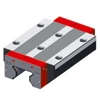 |  |  |  |  |
| Standard Standard | Standard long Standard long | High/flat High/flat | High/flat long High/flat long | Flat Flat | Flat long Flat long |
Carriage Dimensional Drawing MR W 55

Carriage Specifications MR W 55
| Parameter | MR W 55-A | MR W 55-B | MR W 55-C | MR W 55-D | MR W 55-F | MR W 55-G |
|---|---|---|---|---|---|---|
| System Height A (mm) | 70 | 70 | 80 | 80 | 70 | 70 |
| Carriage Width B (mm) | 140 | 140 | 100 | 100 | 100 | 100 |
| Reference Surface Distance B2 (mm) | 43.5 | 43.5 | 23.5 | 23.5 | 23.5 | 23.5 |
| Carriage Height J (mm) | 57 | 57 | 67 | 67 | 57 | 57 |
| Carriage Length L (mm) | 172 | 214 | 172 | 214 | 172 | 214 |
| Outer Fixing Hole Pitch L1 (mm) | 95 | 95 | 75 | 95 | 75 | 95 |
| Inner Fixing Hole Pitch L2 (mm) | 70 | 70 | — | — | — | — |
| Steel Body Length L6 (mm) | 120 | 162 | 120 | 162 | 120 | 162 |
| Side Fixing Hole Pitch N (mm) | 116 | 116 | 75 | 75 | 75 | 75 |
| Reference Surface Height O (mm) | 12 | 12 | 12 | 12 | 12 | 12 |
| Carriage Weight (kg) | 5.0 | 6.8 | 4.5 | 6.1 | 3.7 | 4.8 |
Rigidity Curves and Load Rating Diagrams

Load Ratings
| Carriage Type | C₀ Static Load (N) | C₁₀₀ Dynamic Load (N) | M₀Q Static Cross Moment (Nm) | M₀L Static Long. Moment (Nm) | MQ Dynamic Cross Moment (Nm) | ML Dynamic Long. Moment (Nm) |
|---|---|---|---|---|---|---|
| A / C / F | 237,000 | 131,900 | 7,771 | 4,738 | 4,325 | 2,637 |
| B / D / G | 324,000 | 180,500 | 10,624 | 8,745 | 5,919 | 4,872 |
Available Options
Accuracy Classes
| Accuracy Class | Carriage & Rail Tolerance A/B2 | Matched Carriage Max Difference ΔA/ΔB2 | Standard Carriage Max Difference |
|---|---|---|---|
| G0 Highly accurate | ± 5 µm | 3 µm | 10 µm |
| G1 Very accurate | ± 10 µm | 5 µm | 20 µm |
| G2 Accurate | ± 20 µm | 7 µm | 40 µm |
| G3 Standard | ± 30 µm | 25 µm | 60 µm |
Preload Classes
| Preload Class | Preload Force (% of C₀) | Application |
|---|---|---|
| V0 Very light preload | 0-2% | Very low friction, uniform load, minimum vibration |
| V1 Light preload | 3% | Low friction, uniform load, slight vibration |
| V2 Medium preload | 8% | High rigidity, moderate varying loads and vibration |
| V3 High preload | 13% | Maximum rigidity, impact loads, severe varying loads |
Coating
| Code | Type | Features |
|---|---|---|
| — | Standard (no coating) | Standard steel surface |
| CN | Hard chromium | Excellent corrosion resistance, high wear resistance, good emergency running properties |
Reference Side
R1 - Reference at bottom R2 - Reference on top
Order Code Examples
Rail Order Code
MR S 55-N-G1-KC-R1-1500-35-35-CN
- MR S 55 = MONORAIL Rail Size 55
- N = Standard type
- G1 = Very accurate
- KC = Fixing holes with countersink
- R1 = Reference at bottom
- 1500 = Rail length 1500mm
- 35-35 = First/last hole positions
- CN = Hard chromium coating
Carriage Order Code
MR W 55-A-G1-V2-R1-CN-S11-LV
- MR W 55 = MONORAIL Carriage Size 55
- A = Standard type
- G1 = Very accurate
- V2 = Medium preload (8% C₀)
- R1 = Reference at bottom
- CN = Hard chromium coating
- S11 = Lubrication hole position top center
- LV = Full greasing as delivered