6.6.3 Shielding for the SCHNEEBERGER Distance Measuring System
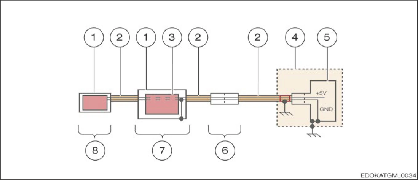
Figure 6.xx - SCHNEEBERGER Shielding Design
1 Housing
2 Cable shield
3 Electronic switch
4 Control cabinet
5 Motor controller
6 Connector
7 Electronic housing
8 Reading head
The housing with cable shielding forms a closed Faraday cage. The cable shield is connected to the connector housing. To ground the measuring system, the outer shield of the cable must be connected to ground in the switch cabinet, so interference currents can be released in this way. In the switch cabinet or controller, 0 V = GND is connected to ground (protective ground line). By using EMC-compliant cable glands, the transition from cable shield to housing can also be achieved at low impedance. Otherwise, in the electronic housing, 0V is connected to the shield, which means interference can also be effectively transferred to the power cable.