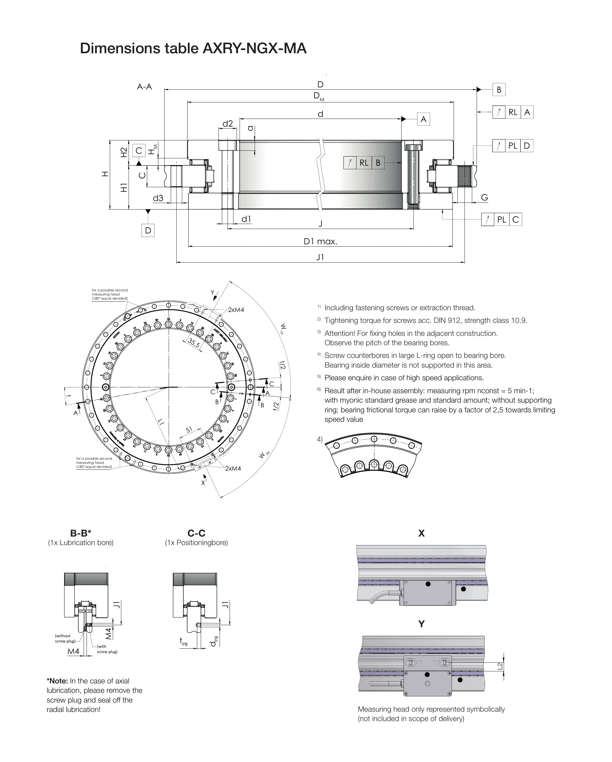
Dimension Notation Drawing
(Click the image to enlarge)
Main Dimensions
The table below lists the main dimensions of all AXRY-NGX-MA models. Dimensions are in mm; weights are in kg.
- d: Bore diameter (shaft journal diameter)
- D: Outside diameter (housing bore diameter)
- H: Total height
- H1: Table-side height
- H2: Shaft-side height
- * Includes standard tolerance / restricted tolerance (restricted tolerance is optional)
- 4) The large L-ring screw counterbore opens toward the bearing bore; this area does not support the bearing inner diameter
| Model | Weight [kg] | d (Bore) | D (Outside) | H [mm] | H1 [mm] | H2 [mm] | ||||
|---|---|---|---|---|---|---|---|---|---|---|
| mm | Tol. | mm | Tol. | mm | Tol. | mm | Tol. | |||
| AXRY 180-NGX-MA | - | 180 | -0.013 | 280 | -0.018 | 50 | 29 | ±0.03 | 21 | ±0.025 |
| AXRY 200-NGX-MA | 9.9 | 200 | -0.015 | 300 | -0.018 | 51 | 30 | ±0.03 | 21 | ±0.025 |
| AXRY 260-NGX-MA | 18.4 | 260 | -0.018 | 385 | -0.020 | 57.5 | 36.5 | ±0.04 | 21 | ±0.025 |
| AXRY 325-NGX-MA4) | 25.2 | 325 | -0.023 | 450 | -0.023 | 61 | 40 | ±0.05 | 21 | ±0.025 |
| AXRY 395-NGX-MA | 32.6 | 395 | -0.023 | 525 | -0.028 | 65 | 42.5 | ±0.05 | 22.5 | ±0.025 |
| AXRY 460-NGX-MA | 45.3 | 460 | -0.023 | 600 | -0.028 | 70 | 46 | ±0.06 | 24 | ±0.03 |
| AXRY 580-NGX-MA | 86.3 | 580 | -0.025 | 750 | -0.035 | 90 | 60 | ±0.25 / ±0.075* | 30 | ±0.25 / ±0.03* |
| AXRY 650-NGX-MA | 165.3 | 650 | -0.038 | 870 | -0.050 | 122 | 78 | ±0.25 / ±0.1* | 44 | ±0.25 / ±0.03* |
Measuring Ring Dimensions
- C: Measuring ring radial installation depth (mm)
- D1 max: Maximum permissible installation diameter (mm)
- J: Measuring ring inner installation clearance (mm)
- J1: Measuring ring outer installation clearance (mm)
- DM: Measuring ring diameter (mm)
- HM: Measuring ring height (mm)
| Model | C [mm] | D1 max [mm] | J [mm] | J1 [mm] | DM [mm] | HM [mm] |
|---|---|---|---|---|---|---|
| AXRY 180-NGX-MA | 15 | 244 | 194 | 260 | 245.1 | 6 |
| AXRY 200-NGX-MA | 15 | 274 | 215 | 285 | 274.3 | 6 |
| AXRY 260-NGX-MA | 18 | 345 | 280 | 365 | 346.9 | 6 |
| AXRY 325-NGX-MA4) | 20 | 415 | 342 | 430 | 415.1 | 6 |
| AXRY 395-NGX-MA | 20 | 486 | 415 | 505 | 487.7 | 6 |
| AXRY 460-NGX-MA | 22 | 560 | 482 | 580 | 560.9 | 9 |
| AXRY 580-NGX-MA | 30 | 700 | 610 | 720 | 699.7 | 9 |
| AXRY 650-NGX-MA | 34 | 800 | 680 | 830 | 799.0 | 21 |
Fixing Holes
- d1: Inner ring screw clearance hole diameter (mm)
- d2: Inner ring screw counterbore diameter (mm)
- a: Inner ring screw counterbore depth (mm)
- d3: Outer ring screw clearance hole diameter (mm)
- Extraction thread: Extraction thread specification per ring
- n × t: Number of fixing holes × pitch angle1)
- MA: Screw tightening torque2) (Nm)
- 3) Fixing holes in the surrounding structure must follow the bearing hole pitch
| Model | Inner Ring Fixing Holes | Outer Ring Fixing Holes | Extraction Thread | n × t1) | MA2) [Nm] | ||||
|---|---|---|---|---|---|---|---|---|---|
| d1 | d2 | a | Qty3) | d3 | Qty3) | ||||
| AXRY 180-NGX-MA | 7 | 11 | 6.4 | 46 | 7 | 45 | M8 | 48 × 7.5° | 14 |
| AXRY 200-NGX-MA | 7 | 11 | 6.4 | 46 | 7 | 45 | M8 | 48 × 7.5° | 14 |
| AXRY 260-NGX-MA | 9.3 | 15 | 8.6 | 34 | 9.3 | 33 | M12 | 36 × 10° | 34 |
| AXRY 325-NGX-MA4) | 9.3 | 15 | 8.6 | 34 | 9.3 | 33 | M12 | 36 × 10° | 34 |
| AXRY 395-NGX-MA | 9.3 | 15 | 8.6 | 46 | 9.3 | 45 | M12 | 48 × 7.5° | 34 |
| AXRY 460-NGX-MA | 9.3 | 15 | 8.6 | 46 | 9.3 | 45 | M12 | 48 × 7.5° | 34 |
| AXRY 580-NGX-MA | 11.4 | 18 | 10.6 | 46 | 11.4 | 42 | M12 | 48 × 7.5° | 68 |
| AXRY 650-NGX-MA | 14 | 20 | 12.6 | 46 | 14 | 42 | M12 | 48 × 7.5° | 116 |
Positioning & Measuring Head
- dPB: Positioning hole diameter (mm)
- tPB: Positioning hole depth (mm)
- L1: Measuring head axial mounting thread spacing (mm)
- Wax: Measuring head axial mounting angular position
- L2: Measuring head radial mounting thread spacing (mm)
- Wra: Measuring head radial mounting angular position
| Model | Positioning Hole | Measuring Head Mounting Thread | ||||
|---|---|---|---|---|---|---|
| dPB [mm] | tPB [mm] | L1 [mm] | Wax | L2 [mm] | Wra | |
| AXRY 180-NGX-MA | 5 | 5 | 127.0 | 56.25° | 7.5 | 63.75° |
| AXRY 200-NGX-MA | 5 | 5 | 141.6 | 56.25° | 7.5 | 63.75° |
| AXRY 260-NGX-MA | 5 | 5 | 177.2 | 60° | 9 | 65° |
| AXRY 325-NGX-MA4) | 5 | 5 | 212.5 | 55° | 10 | 65° |
| AXRY 395-NGX-MA | 5 | 5 | 249.0 | 60° | 10 | 63.75° |
| AXRY 460-NGX-MA | 5 | 5 | 285.6 | 56.25° | 11 | 63.75° |
| AXRY 580-NGX-MA | 8 | 8 | 355.0 | 56.25° | 15 | 63.75° |
| AXRY 650-NGX-MA | 10 | 10 | 404.7 | 56.25° | 17 | 63.75° |
Load Ratings
- Ca: Dynamic axial load rating (kN)
- C0a: Static axial load rating (kN)
- Cr: Dynamic radial load rating (kN)
- C0r: Static radial load rating (kN)
- Cal: Axial stiffness (kN/μm)
- Crl: Radial stiffness (kN/μm)
- Ckl: Tilting stiffness (kNm/mrad)
| Model | Axial Load Rating | Radial Load Rating | Stiffness | ||||
|---|---|---|---|---|---|---|---|
| Ca [kN] | C0a [kN] | Cr [kN] | C0r [kN] | Cal [kN/μm] | Crl [kN/μm] | Ckl [kNm/mrad] | |
| AXRY 180-NGX-MA | 139.3 | 755.0 | 99.4 | 200.3 | 9.0 | 3.2 | 57.2 |
| AXRY 200-NGX-MA | 151.0 | 871.2 | 122.1 | 273.9 | 8.9 | 4.1 | 69.7 |
| AXRY 260-NGX-MA | 220.1 | 1520.6 | 138.3 | 349.0 | 12.7 | 5.1 | 159.4 |
| AXRY 325-NGX-MA4) | 249.3 | 1900.8 | 181.7 | 531.4 | 15.4 | 7.2 | 275.8 |
| AXRY 395-NGX-MA | 275.7 | 2281.0 | 199.2 | 633.8 | 18.3 | 8.4 | 459.4 |
| AXRY 460-NGX-MA | 299.5 | 2661.1 | 232.5 | 739.0 | 21.9 | 8.6 | 736.9 |
| AXRY 580-NGX-MA | 584.6 | 4457.4 | 284.5 | 867.2 | 22.9 | 8.8 | 1207.0 |
| AXRY 650-NGX-MA | 1010.7 | 7682.4 | 459.6 | 1317.1 | 27.1 | 9.7 | 1880.1 |
Speed & Friction
- nG: Limiting speed5) (min-1)
- MR: Friction torque6) (Nm)
| Model | nG5) [min-1] | MR6) [Nm] |
|---|---|---|
| AXRY 180-NGX-MA | 600 | 5 |
| AXRY 200-NGX-MA | 450 | 6 |
| AXRY 260-NGX-MA | 300 | 9 |
| AXRY 325-NGX-MA4) | 200 | 13 |
| AXRY 395-NGX-MA | 200 | 19 |
| AXRY 460-NGX-MA | 150 | 25 |
| AXRY 580-NGX-MA | 80 | 60 |
| AXRY 650-NGX-MA | 70 | 70 |
Runout
- PL: Axial runout (Plan Lauf, μm)
- RL: Radial runout (Radial Lauf, μm)
| Model | Standard PL & RL [μm] | Restricted PL & RL [μm] |
|---|---|---|
| AXRY 180-NGX-MA | 4 | 2 |
| AXRY 200-NGX-MA | 4 | 2 |
| AXRY 260-NGX-MA | 6 | 3 |
| AXRY 325-NGX-MA4) | 6 | 3 |
| AXRY 395-NGX-MA | 6 | 3 |
| AXRY 460-NGX-MA | 6 | 3 |
| AXRY 580-NGX-MA | 10 | 5 |
| AXRY 650-NGX-MA | 10 | 5 |
Measuring Ring Specifications
- Graduations/360°: Number of graduations per revolution of the measuring ring (Teilstriche/U); 1000 μm pitch
- Pitch accuracy ±3 μm: Pitch accuracy in arc seconds (") corresponding to ±3 μm arc length
- Pitch accuracy ±5 μm: Pitch accuracy corresponding to ±5 μm arc length
| Model | Graduations/360° | Pitch accuracy ±3 μm ["] | Pitch accuracy ±5 μm ["] |
|---|---|---|---|
| AXRY 180-NGX-MA | 768 | 5.1 | 8.4 |
| AXRY 200-NGX-MA | 860 | 4.5 | 7.5 |
| AXRY 260-NGX-MA | 1088 | 3.6 | 6.0 |
| AXRY 325-NGX-MA4) | 1302 | 3.0 | 5.0 |
| AXRY 395-NGX-MA | 1530 | 2.5 | 4.2 |
| AXRY 460-NGX-MA | 1760 | 2.2 | 3.7 |
| AXRY 580-NGX-MA | 2196 | 1.8 | 3.0 |
| AXRY 650-NGX-MA | 2508 | 1.6 | 2.6 |
The absolute measuring system achieves up to ±1 μm arc-length accuracy and knows its position immediately on power-up, without reference travel.
Distance Plate Recommendation
To mount the absolute measuring head directly onto the bearing outer ring, a distance plate must be used depending on the model. The bearing outer ring is pre-provided with M4 threads spaced 51 mm apart.
- DP-H: Distance plate height (mm); blank means no distance plate is required
| Bearing Model | Size Range | DP-H [mm] |
|---|---|---|
| AXRY | 180 – 395 | Not required |
| AXRY | 460 | 3 |
| AXRY | 580 | 3 |
| AXRY | 650 | 15 |
Lubrication Bores
The bearing uses the following section configurations; these symbols appear in the engineering drawing:
- B-B*: 1 × lubrication bore. For axial lubrication, remove the screw plug and seal the radial lubrication bore.
- C-C: 1 × positioning hole (Positionierbohrung).
The bearing outer ring is provided with 2 × M4 threads (51 mm pitch) for mounting the measuring head. A second measuring head can be mounted at the 180° opposite position (dual-head configuration).
AMO Reading Head Dimensions
The AXRY-MA absolute measuring system uses AMO WMKA-2010 series reading heads (Abtastkopf) together with the WMBA-1010 scale. The scale consists of a measuring tape (grating ring, #0.3 mm) and a cover tape (#0.05 mm) and is mounted directly on the bearing inner ring. Reading heads are available in two mounting types according to cable exit and mounting direction — radial and axial:
| Mounting type | Reading head | Cable exit | Applicable sizes |
|---|---|---|---|
| Radial design | WMKA-2010-52 / -53 | Tangential cable exit | 150 – 650 |
| WMKA-2010-54 | Radial cable exit | 150 – 650 | |
| Axial design | WMKA-2010-55 | Cable exit on one side | 150 – 460 |
| WMKA-2010-56 | Cable exit on the other side | 150 – 460 |
Scale designation: WMBA-1010-XXXX-SXX, where XXXX is the number of graduations per revolution (Teilstriche/U), identical to the line count in the "Measuring Ring Specifications" section on this page. Air gap: 0.15 ±0.1 mm.
Radial Reading Head WMKA-2010-52/53/54
The reading head is mounted on the housing surface of the bearing outer ring, so the air gap can be set directly via the outer ring diameter without complex gap adjustment. Common mounting geometry: head width 50 ±0.10 mm, overall height 14 (0/−0.05) mm, mounting face 6 ±0.50 mm, head body approx. 40 × 31 mm. Types 52 and 53 have a tangential cable exit; type 54 has a radial cable exit.
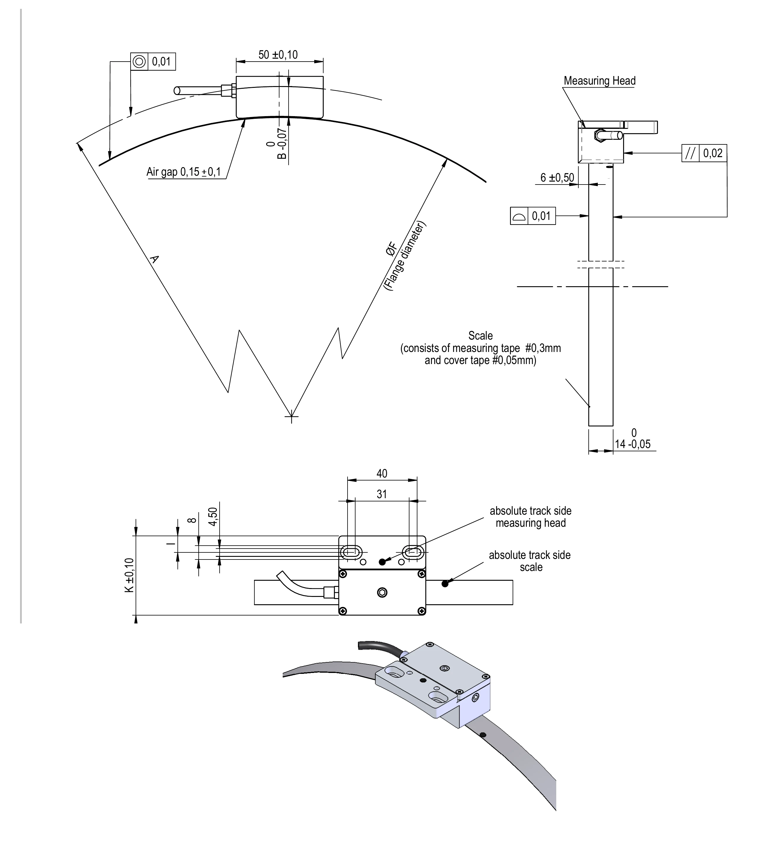
Radial reading head dimensions (with cross-section, head detail and mounting illustration; example type WMKA-2010-53)
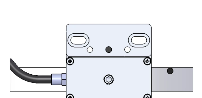
WMKA-2010-53
Tangential cable exit
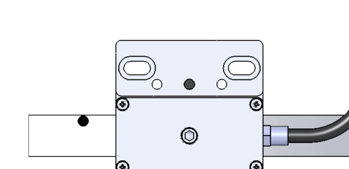
WMKA-2010-52
Tangential cable exit (opposite side)
WMKA-2010-54
Radial cable exit
- ØF: Flange diameter (Flansch Durchmesser, mm)
- A, B, I, K: See the dimension drawing above for measurement locations
- Size code: Number of graduations per revolution of the measuring ring (Teilstriche/U)
| No. | Bearing | Size code (grating/rev) | ØF [mm] | A [mm] | B (0/−0.07) [mm] | I [mm] | K (±0.1) [mm] |
|---|---|---|---|---|---|---|---|
| 1 | AXRY 150 | 0672 | 213.77 ±0.02 | 120 | 12.61 | 5.5 | 37.5 |
| 2 | AXRY 180 | 0768 | 244.36 ±0.02 | 140 | 17.32 | 7 | 40.5 |
| 3 | AXRY 200 | 0860 | 273.65 ±0.02 | 150 | 12.67 | 7 | 40.5 |
| 4 | AXRY 260 | 1088 | 346.24 ±0.03 | 192.5 | 18.88 | 7.5 | 42.5 |
| 5 | AXRY 325 | 1302 | 414.36 ±0.03 | 225.0 | 17.32 | 9.5 | 45.5 |
| 6 | AXRY 395 | 1530 | 486.96 ±0.06 | 262.5 | 18.52 | 9.5 | 45.5 |
| 7 | AXRY 460 | 1760 | 560.18 ±0.06 | 300 | 19.41 | 10.5 | 50.5 |
| 8 | AXRY 580 | 2196 | 698.99 ±0.07 | 375 | 25 | 14 | 58 |
| 9 | AXRY 650 | 2508 | 799.30 ±0.07 | 435 | 35.35 | 12 | 70 |
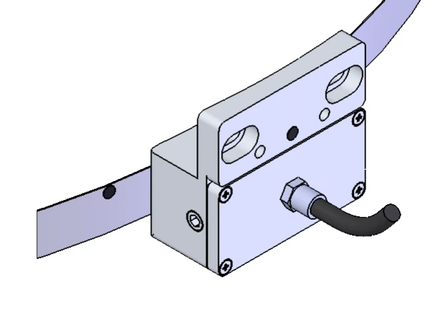
Axial Reading Head WMKA-2010-55/56
The axial reading head is fixed with 2 × M4 screws (counterbore 2 × Ø4.5 mm / through-hole 2 × Ø4.9 mm, screw pitch 51 mm), cable diameter Ø4.5 mm, head height 26 (0/−0.06) mm. The 0.15 ±0.1 mm air gap is set using a 0.15 mm shim (Folie). Types 55 and 56 differ only in the cable exit side. Applicable sizes 150 – 460.
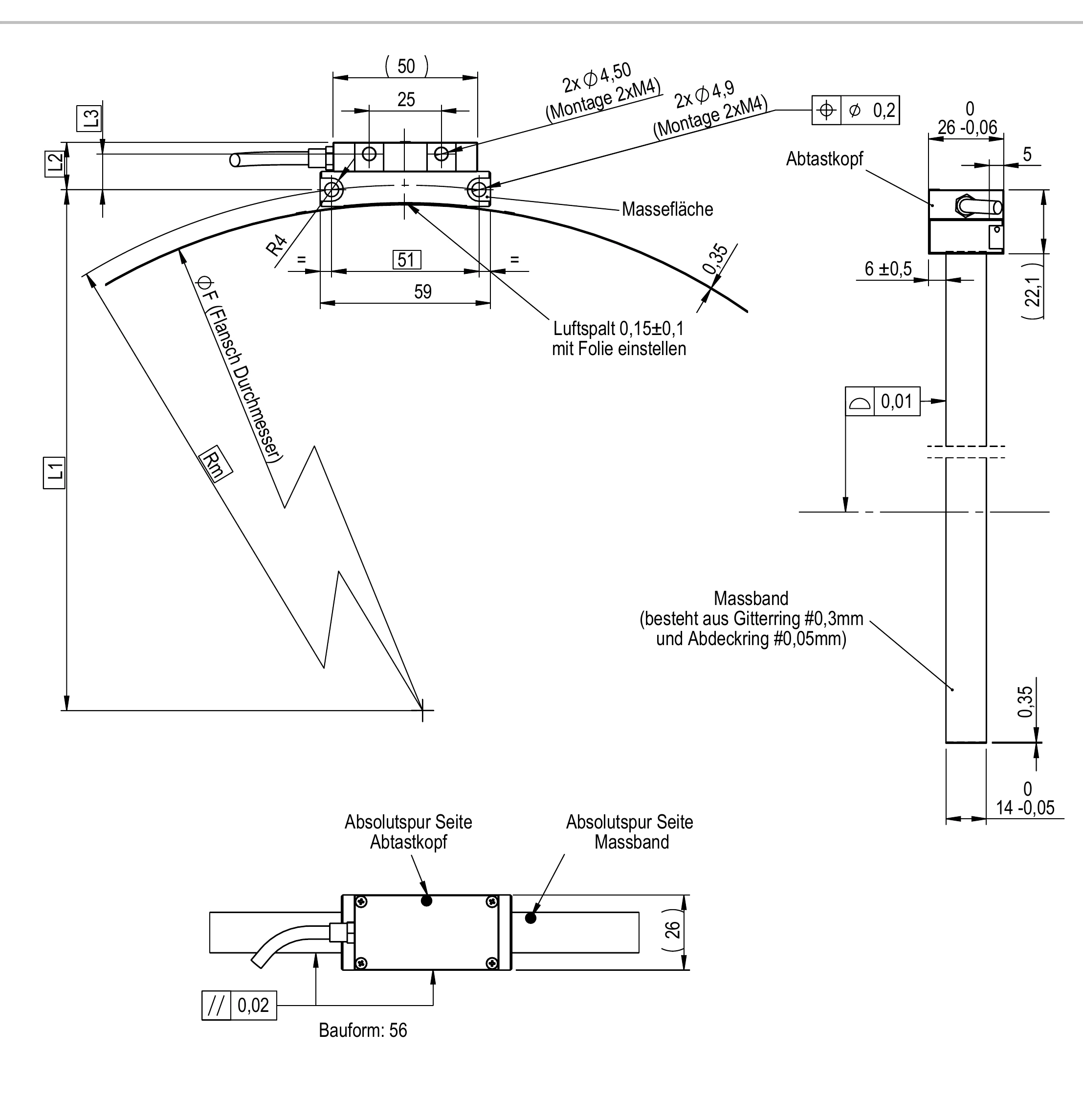
Axial reading head dimensions (original German engineering drawing; callouts explained below)
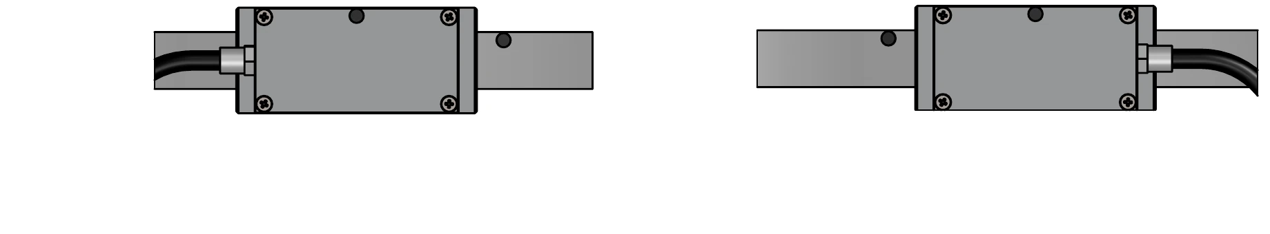
WMKA-2010-56 (left) and WMKA-2010-55 (right), opposite cable exit sides
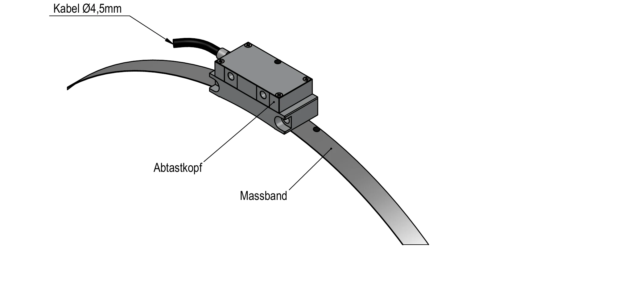
Reading head mounted on the scale (Massband)
- ØF: Flange diameter (Flansch Durchmesser, mm)
- L1, L2, L3, Rm: See the dimension drawing above for measurement locations
- Size code: Number of graduations per revolution of the measuring ring (Teilstriche/U)
| No. | Bearing | Size code (grating/rev) | ØF [mm] | L1 [mm] | Rm | L2 [mm] | L3 [mm] |
|---|---|---|---|---|---|---|---|
| 1 | AXRY 150 | 0672 | 213.77 ±0.02 | 111.69 | 114.60 | 16.4 | 12.4 |
| 2 | AXRY 180 | 0768 | 244.36 ±0.02 | 126.98 | 129.50 | 16.4 | 12.4 |
| 3 | AXRY 200 | 0860 | 273.65 ±0.02 | 141.62 | 143.90 | 16.4 | 12.4 |
| 4 | AXRY 260 | 1088 | 346.24 ±0.03 | 177.17 | 179.00 | 17.6 | 13.6 |
| 5 | AXRY 325 | 1302 | 414.36 ±0.03 | 212.48 | 214.00 | 16.4 | 12.4 |
| 6 | AXRY 395 | 1530 | 486.96 ±0.06 | 248.98 | 250.30 | 16.4 | 12.4 |
| 7 | AXRY 460 | 1760 | 560.18 ±0.06 | 285.56 | 286.70 | 16.4 | 12.4 |
Scope of delivery: reading head (WMKA-2010-55 or -56) + ISO 4762 M4×30 socket head cap screws + 0.15 mm adjustment shim (Abstandsfolie).
1) Including clamping screw or extraction thread.
2) Screw tightening torque per DIN 912, strength class 10.9.
3) Note! Fixing holes in the surrounding structure must follow the bearing hole pitch.
4) The large L-ring screw counterbore opens toward the bearing bore; this area does not support the bearing inner diameter.
5) For high-speed applications, please consult sales@eb-system.com.
6) Measured after internal assembly: measuring speed nconst = 5 min-1; using myonic standard grease and standard quantity; without support ring; the bearing friction torque may increase by up to 2.5× at the limiting speed.