Service Life and Load Safety Factor
Nominal Service Life
The calculation of the nominal service life takes place via special calculation programs. You are welcome to request our technical questionnaire for this purpose by writing to sales@eb-system.com. The calculation itself is conducted by our employees in application engineering.
Information Required for myonic Calculation
- Details on application (drawings, sketches, technical specifications)
- Workpiece dimensions and weight
- Details on the load cycle (cutting forces, speeds, operating durations)
Static Load Safety Factor
The static load safety factor S0 describes the safety prior to unpermitted plastic deformations of the bearing components in the roller area.
In the case of purely axial or radial forces, the static load safety can be inspected separately via the following formulas:
S0 = C0r / F0r or S0 = C0a / F0a
| Symbol | Description |
|---|---|
| S0 | Static load safety factor (should be >4 for machine tool applications) |
| C0r | Static load rating, radial [N] (acc. dimension tables) |
| C0a | Static load rating, axial [N] (acc. dimension tables) |
| F0r | Maximum static load of the radial bearing [N] |
| F0a | Maximum static load of the axial bearing [N] |
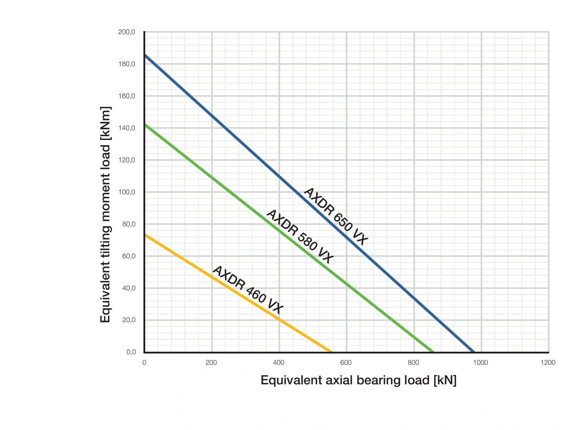
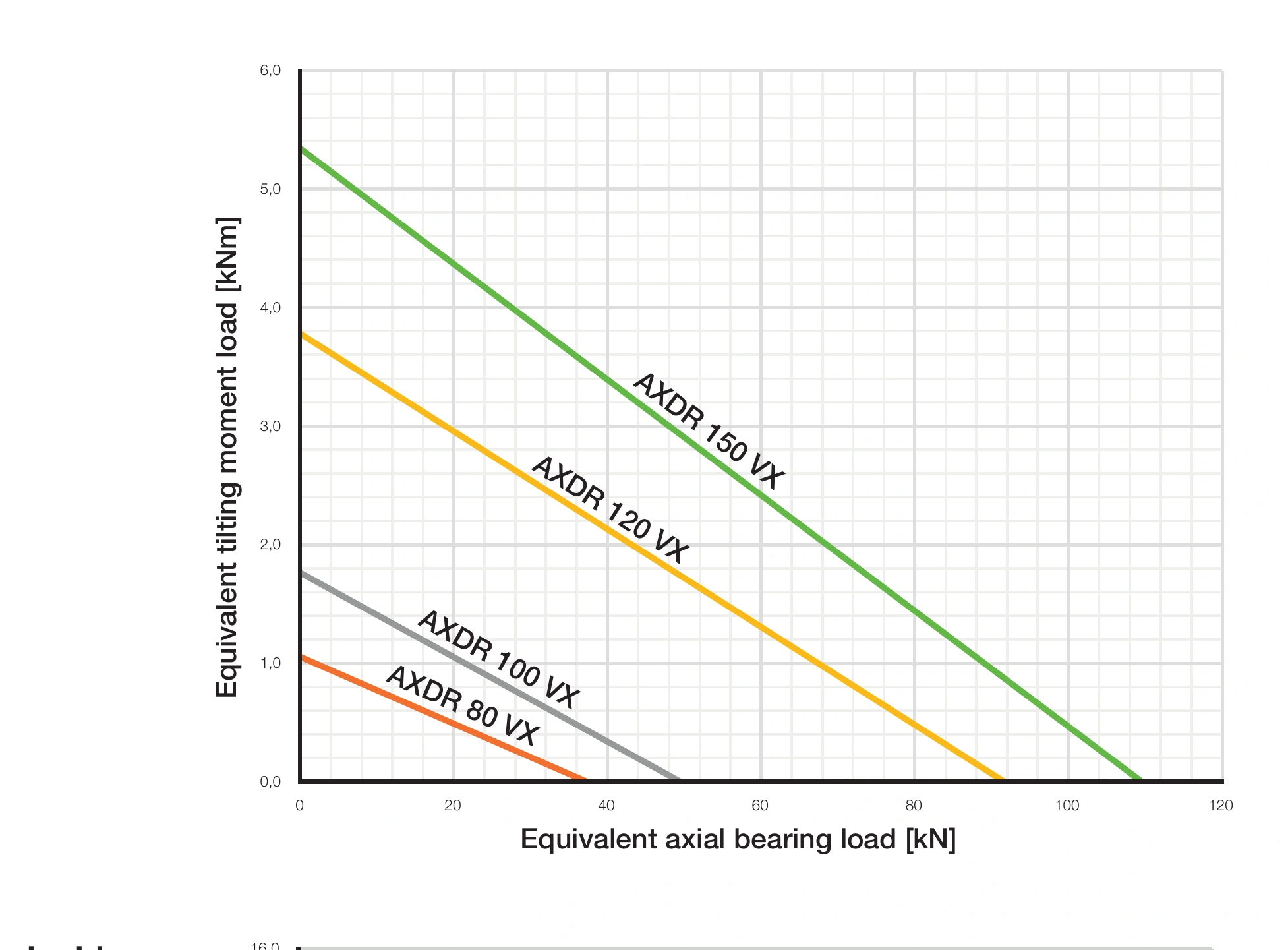
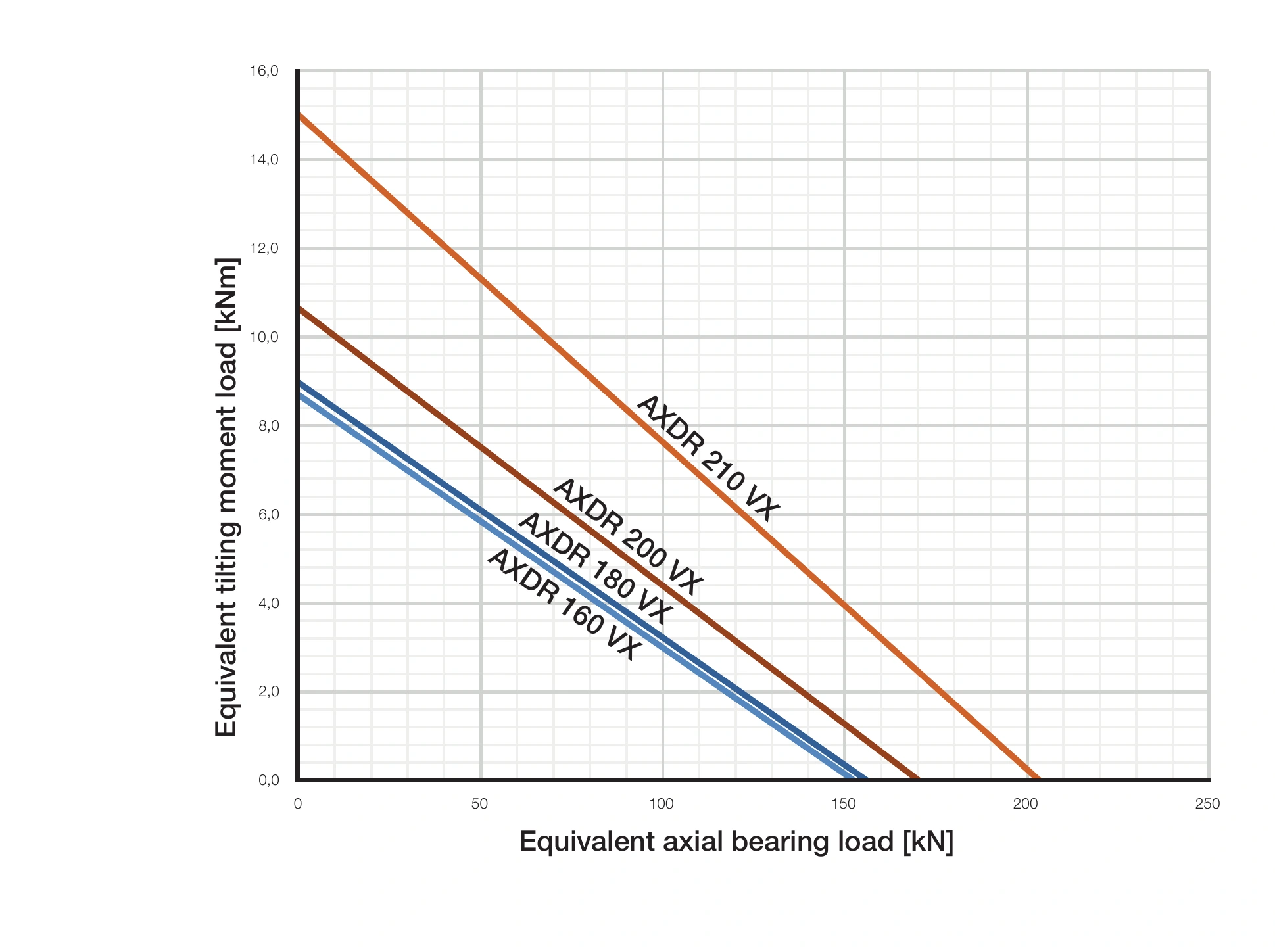
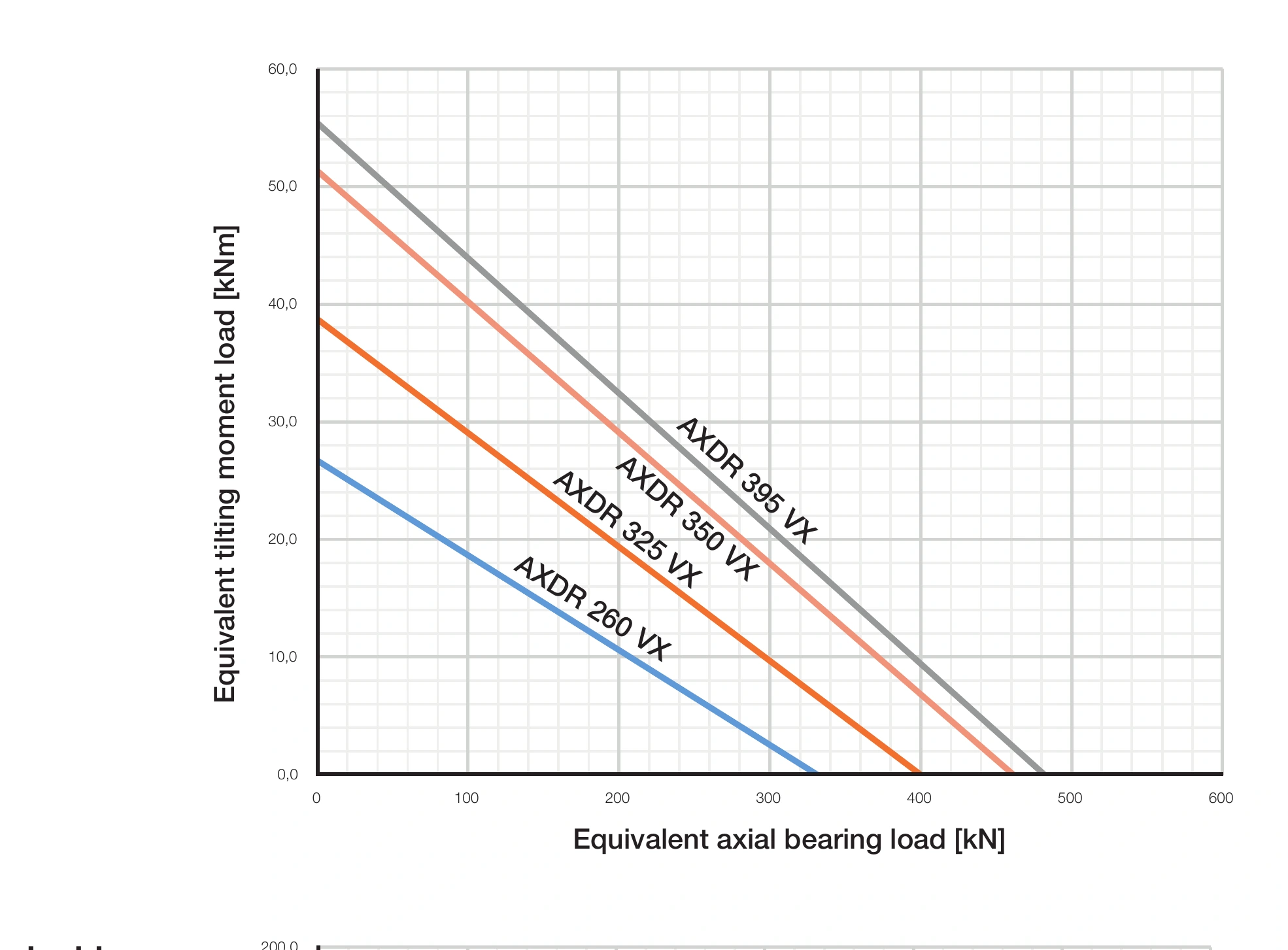
Static Limiting Load Diagrams
In most applications, tilting moments are added to the radial or axial forces. With the aid of the following static limiting load diagrams, the correct bearing size for bearings with mainly static load can be rapidly selected. Here the required load safety factor S0 = 4 is already taken into account in the diagrams for the roller element set as well as the screw and bearing ring strength; therefore, as long as the selected operating point lies within the permitted range (below the curve), S0 ≥ 4 is ensured.
Advantages
- Easy selection of the bearing size with mainly static load
- Determination of the possible tilting moment Mk that can be absorbed in addition to the axial load

- X-axis: Equivalent axial bearing load [kN]
- Y-axis (Mk): Maximum tilting torque [kNm]
- 1: Bearing/size curve
- 2: Permitted range
- 3: Unpermitted range
Note
AXDR double row angular contact roller bearings and AXRY axial/radial bearings have been calculated under the same framework conditions, so both bearing types are directly comparable with each other, as long as the adjacent construction is designed according to the myonic catalogue data.
AXDR 80 VX to AXDR 150 VX Limiting Load Diagrams
AXDR 160 VX to AXDR 210 VX Limiting Load Diagrams
AXDR 260 VX to AXDR 395 VX Limiting Load Diagrams
AXDR 460 VX to AXDR 650 VX Limiting Load Diagrams