General
Through a purely inductive measuring system, maximum system accuracies of less than ±2 µm arc length can be achieved.
The measuring system consists of a solid measuring ring with incremental code together with a measuring head incorporating a sensor and analog-to-digital evaluation electronics. Depending on the requirements, single-head or multi-head scanners are available. The measuring ring is mounted directly on the bearing inner ring.
The integrated measuring system is available for sizes 150 to 650. For some sizes the overall height is greater than the standard bearing without measuring system (see product tables). The measuring head is integrated into the surrounding structure, or mounted directly on the outer ring using a distance plate. The distance plate must be provided by the customer.
Characteristics
Size and Encoding
- Available from size 150 to 650 mm
- Incremental encoding
Measuring Head
- Miniature measuring head with minimal installation dimensions
- Single-head and multi-head scanner options
- Multi-head scanning eliminates eccentricity and radial runout errors
Environmental Performance
- Dust protection rating IP67
- Resistant to magnetic interference fields
- Operating temperature −10 °C to +100 °C
Output Signals
- Integrated reference pulse, also distance-coded
- Analog output signal (1VSS), subdivided signal period down to 15 µm
- Digital output RS-422 / TTL, resolution down to 0.125 µm
Single-Head Measurement (Axial)
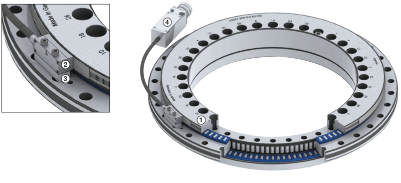
| No. | Component | Description |
|---|---|---|
| 1 | AXRY-MI | Bearing with measuring ring |
| 2 | Measuring Head | Axially mounted inductive measuring head |
| 3 | Distance Plate | For correct positioning of the measuring head |
| 4 | External Evaluation Electronics | Signal processing unit |
Double-Head Measurement (Radial)
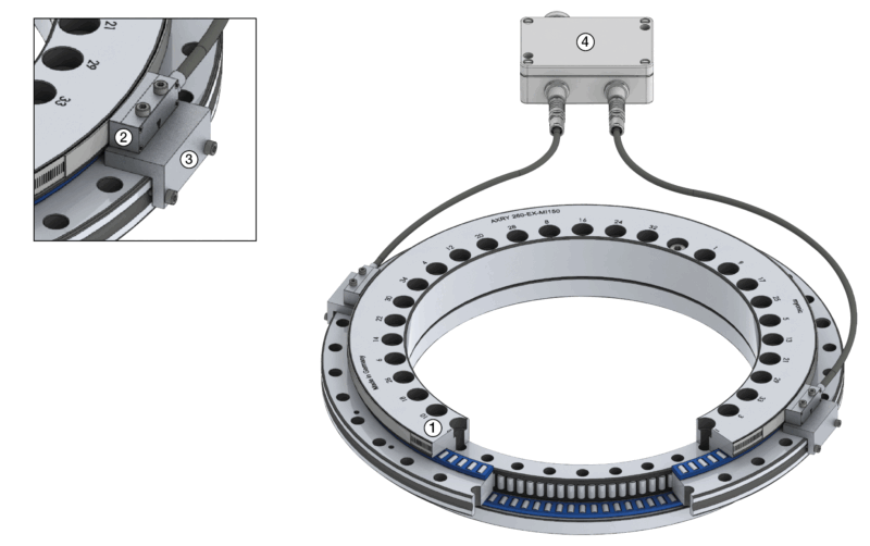
| No. | Component | Description |
|---|---|---|
| 1 | AXRY-MI | Bearing with measuring ring |
| 2 | Measuring Head | Radially mounted inductive measuring head |
| 3 | Distance Plate | For correct positioning of the measuring head |
| 4 | MHS Evaluation Electronics | Multi-head system signal processing unit |
Recommendation Distance Plates for Incremental Measuring Heads
If you wish to mount the incremental measuring head directly onto the bearing outer ring, a distance plate is required. M4 threads at a spacing of 51 mm are already provided on the bearing outer ring. These threads are suitable for absolute measuring heads as well as for mounting the distance plate used for incremental measuring heads (via M3 threads at a spacing of 16 mm).
For the incremental measuring head to measure at the correct position, the two distances DP-L and DP-H must be set using the distance plate.
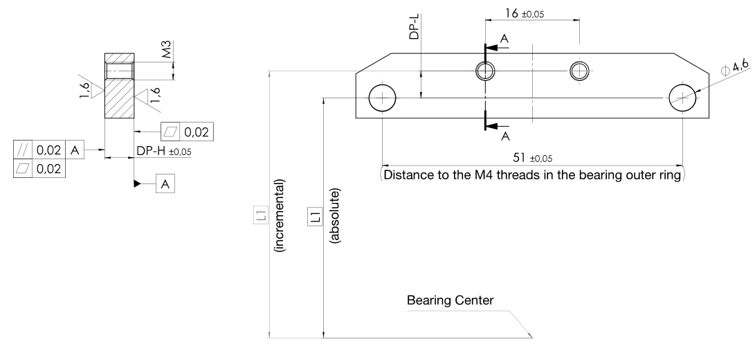
DP-H: distance plate height (vertical direction) | DP-L: distance plate length offset (horizontal direction)
| Bearing Model | DP-H (mm) | DP-L (mm) |
|---|---|---|
| AXRY 150 | 5 | 4.56 |
| AXRY 180 | 5 | 4.62 |
| AXRY 200 | 5 | 4.60 |
| AXRY 260 | 7 | 4.07 |
| AXRY 325 | 7 | 4.10 |
| AXRY 395 | 7 | 2.29 |
| AXRY 460 | 9 | 2.65 |
| AXRY 580 | 14 | 4.53 |
| AXRY 650 | 20 | 2.63 |