When selecting a carriage type, in addition to load capacity, the fixing type and available installation space are particularly important. This chapter provides an overview of MONORAIL MR roller and MONORAIL BM ball carriage types, as well as detailed characteristic analysis for carriage selection. All carriage types comply with DIN 645 standard in external dimensions and lubrication fixing hole positions, and are therefore interchangeable.
4.4.1 Carriage Types Overview
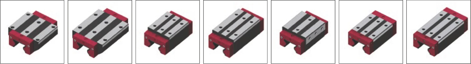
When selecting a carriage type, in addition to load capacity, the fixing type and available installation space are particularly important. The following table provides an overview of MONORAIL MR roller and MONORAIL BM ball types. For available sizes, please refer to the SCHNEEBERGER MONORAIL and AMS product catalog. All carriage types comply with DIN 645 standard in external dimensions and lubrication fixing hole positions, and are therefore interchangeable.
BM Carriage Product Overview

| Size / Carriage Type | |||||||
|---|---|---|---|---|---|---|---|
| A Standard | B Standard Long | C Compact High | D Compact Long | E Compact High | F Compact | G Compact Side fixing | |
| Size 15 | BM W 15-A | BM W 15-C | BM W 15-F | ||||
| Size 20 | BM W 20-A | BM W 20-B | BM W 20-C | BM W 20-D | |||
| Size 25 | BM W 25-A | BM W 25-B | BM W 25-C | BM W 25-D | BM W 25-E | BM W 25-F | BM W 25-G |
| Size 30 | BM W 30-A | BM W 30-B | BM W 30-C | BM W 30-D | BM W 30-E | BM W 30-F | BM W 30-G |
| Size 35 | BM W 35-A | BM W 35-B | BM W 35-C | BM W 35-D | BM W 35-E | BM W 35-F | BM W 35-G |
| Size 45 | BM W 45-A | BM W 45-B | BM W 45-C | BM W 45-D | BM W 45-F | BM W 45-G | |
| Special Characteristics | |||||||
| Fixing from above | ● | ● | ● | ● | ● | ● | |
| Fixing from below | ● | ● | |||||
| Fixing from side | ● | ||||||
| For high forces and moments | ● | ● | ● | ||||
| For medium forces and moments | ● | ● | ● | ● | |||
| For limited space installation | ● | ● | |||||
MR Carriage Product Overview
| Size / Carriage Type | |||||||
|---|---|---|---|---|---|---|---|
| A Standard | B Standard Long | C Compact High | D Compact Long | E Compact High | F Compact | G Compact Side fixing | |
| Size 25 | MR W 25-A | MR W 25-B | MR W 25-C | MR W 25-D | MR W 25-E | MR W 25-F | MR W 25-G |
| Size 35 | MR W 35-A | MR W 35-B | MR W 35-C | MR W 35-D | MR W 35-E | ||
| Size 45 | MR W 45-A | MR W 45-B | MR W 45-C | MR W 45-D | MR W 45-F | ||
| Size 55 | MR W 55-A | MR W 55-B | MR W 55-C | MR W 55-D | MR W 55-G | ||
| Size 65 | MR W 65-A | MR W 65-B | MR W 65-C | MR W 65-D | |||
| Size 100 | MR W 100-B | ||||||
| Special Characteristics | |||||||
| Fixing from above | ● | ● | ● | ● | ● | ● | |
| Fixing from below | ● | ● | |||||
| Fixing from side | ● | ||||||
| For high forces and moments | ● | ● | ● | ||||
| For medium forces and moments | ● | ● | ● | ● | |||
| For limited space installation | ● | ● | |||||
Legend: ● = This model has this characteristic
4.4.2 Carriage Characteristics and Selection Criteria
Mounting Method
All carriage types have 6 threaded fixing holes and/or through holes for fastening. For carriages, they are designed as blind holes with compact cross-sections (types C, D, F and G), allowing fixing from above, while type E allows fixing from the side.
Carriage types A and B have through threaded fixing holes. They allow fixing from above and below. Fixing from above achieves a more rigid connection due to the larger screw diameter.
When fixing from below, note that medium-sized fixing holes should use low-head screws according to DIN 6912 standard, and if present, plastic protection plugs must be removed from the middle carriage fixing holes. When fixing the carriage, the mounting surface must be completely flat. Otherwise, the flatness of the support surface must comply with the specifications in Section 4.14.5 "Geometric and position accuracy of support surfaces", otherwise carriage deformation will occur, leading to changes in carriage preload.
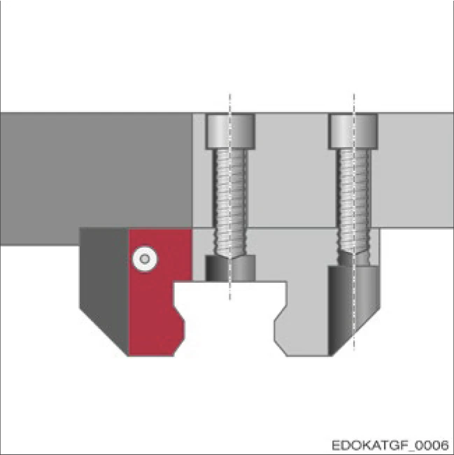
Carriage with through threaded fixing holes fixed from above
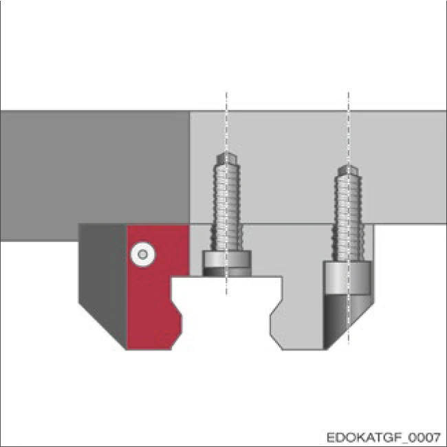
Carriage with through threaded fixing holes fixed from below
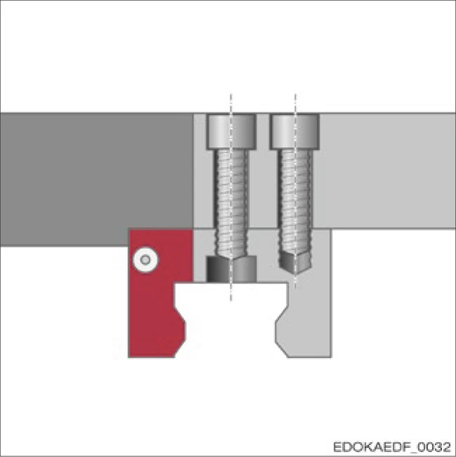
Carriage with blind hole fixing holes fixed from below
Interchangeability
Carriages of the same size can be replaced. Preload remains unchanged. Carriages have different hole patterns depending on the type. Carriage types A and B are an exception. Although they have different lengths, they have the same drilling pattern, which makes interchange possible. Therefore, for example, short (A) and long (B) carriages can be interchanged without modifying the machine slide. This is not possible with all other carriage types.
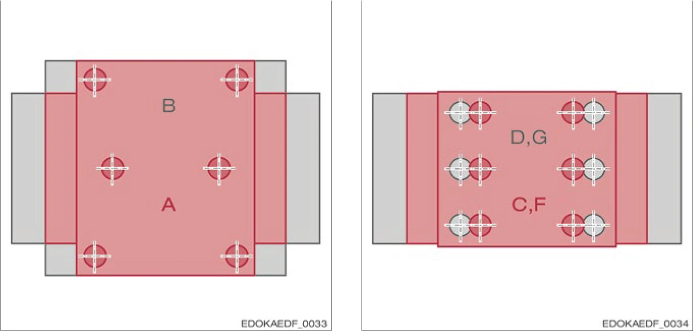
Screw hole drilling pattern for carriage types A and B Screw hole drilling pattern for carriage types C, D, F and G
Types D, G and C, F have the same drilling pattern, but different carriage heights.
Rigidity
In terms of rigidity when using force and moment loads, long carriages (types B, D and G) achieve optimal values based on a large number of load-bearing rolling elements.
The carriage cross-section plays a much smaller role, especially since the rigidity of the carriage in the bolted state is largely achieved through the surrounding structure. For this purpose, especially for tensile loads, it is very important to achieve a rigid connection between the carriage body and the surrounding structure. SCHNEEBERGER provides 6 fixing holes for all its carriage types. This ensures a more rigid connection compared to 4 fixing screws.
For lateral loads, types A and B are preferred because the flange structure achieves better lateral rigidity.
Rigidity Optimization Recommendations
- Long carriages (B, D, G): Optimal rigidity, suitable for high force and moment loads
- Flange types (A, B): Excellent lateral rigidity, suitable for lateral loads
- 6 fixing holes: Ensures rigid connection with surrounding structure
Accuracy
If a high level of running accuracy is required, or when using multi-section guide rails, we recommend using long carriage types B, D and G, because they have lower stroke pulsation than short types A, C and F, and can more effectively compensate for irregularities in the guide rail, such as deformation due to screw force or tolerance of butt transition joints.
When greater elasticity and tolerance to compensate for inaccuracies in angular errors in the connecting structure is required, short carriage types are preferred.
Long Carriages (B, D, G)
- Lower stroke pulsation
- More effective compensation for guide rail irregularities
- Suitable for high precision applications
- Suitable for multi-section guide rail systems
Short Carriages (A, C, F)
- Greater elasticity
- Better tolerance adaptability
- Suitable for angular error compensation
- Suitable for applications with high structural flexibility requirements
Selection Recommendation
When selecting carriage type, consider load capacity, installation space, fixing method, rigidity requirements and accuracy requirements comprehensively. Long carriages are suitable for high load, high precision applications; short carriages are suitable for applications with space constraints and requiring elastic compensation. For detailed selection recommendations, please consult the SCHNEEBERGER technical team.