3.2 Interfaces
3.2.1 Incremental Interfaces
Analogue Voltage Interface (1 VSS)
Products AMSA-3B, AMSA-4B, AMSA-3L
Signal reading head for analogue systems, operational amplifier output, completely differentiated output

Signal reading head for analogue systems, operational amplifier output, completely differentiated output
Symbol legend:
This interface guarantees safe data transmission and is therefore the most widely used interface for incremental measurements. The incremental signals sine and cosine are phase-shifted by 90°. The signal period is 0.2 mm. Due to the signal voltage adjustment AGC (Automatic Gain Control), the level of the incremental signals and the reference signal after differential amplification is always constant at 1 ± 0.2 VSS. Depending on the controller, the switch-off limit is approximately 0.4 VSS to 1.6 VSS.
The reference pulse is symmetrically set at the intersection of the sine and cosine waves (45°). The width and phase of the reference pulse are limited as shown in the diagram. When evaluating the signal, the accuracy of the reference point can be improved by additionally using the incremental information. This interface is suitable for all standard controllers that support a 1 VSS voltage interface. A terminal resistance of 120 ohms should be used. The maximum cable length for the reading head is 30 meters.

Signal waveform of the analogue voltage interface, shown inverted, with a signal period of 200 μm
Pin Layout
TSU/TRU/TMU Interface
| Contact | Signal | Signal type | Supply | Reference | I/O | Min | Typ | Max |
|---|---|---|---|---|---|---|---|---|
| 1 | - Ua2 | - Cosine | ||||||
| 2 | + 5 V sensor | Supply voltage feedback | output | 4.5 V | 5.0 V | 5.5 V | ||
| 3 | + Ua2 | + Cosine | ||||||
| 4 | - Ua0 | Reference signal | ||||||
| 5 | Screen | Screen | - | |||||
| 6 | + Ua0 | + Reference signal | ||||||
| 7 | - Ua1 | - Sine | ||||||
| 8 | + 5 V | Supply voltage | + | input | 4.5 V | 5.0 V | 5.5 V | |
| 9 | + Ua1 | + Sine | ||||||
| 10 | NC | Not connected | ||||||
| 11 | GND | Ground | - | + | ||||
| 12 | - | - | ||||||
| 13 | Screen | Screen |
Digital Interface
Products AMSD-3B and AMSD-4B
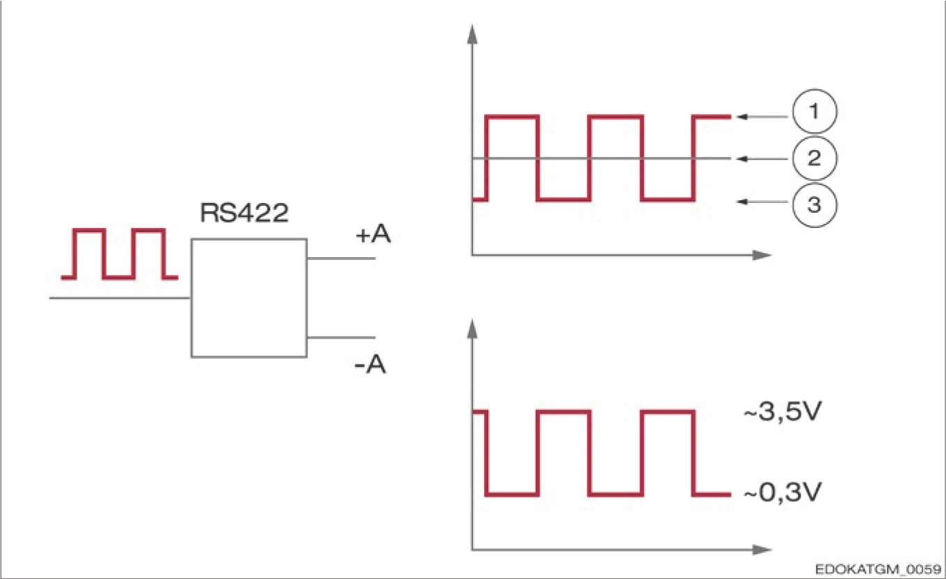
Completely differentiated interface in accordance with EIA-RS 422 standard
In the case of a digital reading head interface, a pair of conductors is used to transmit the signal A+ and the inverted signal A-. Similarly, B+, B- and the reference signal R+, R- are also transmitted differentially. An output driver of type DS34C87TM from National Semiconductor is used here.
The advantage of differential transmission is the enhanced interference immunity through symmetrical transmission of the inverted signal.
Digital systems
Rise and fall times are less than 20 ns. The minimum edge spacing (x) can be calculated from the set maximum output frequency and resolution. The downstream electronics must be able to reliably process the maximum output frequency. The maximum programmable output frequency of the reading head is 8 MHz. Settable resolutions are 0.2 µm / 1 µm / 5 µm.

Signal waveform of the digital interface
TSD/TRD/TMD Interface
| Contact | Signal | Signal type | Supply | Reference | I/O | Min | Typ | Max |
|---|---|---|---|---|---|---|---|---|
| 1 | A- | A- | ||||||
| 2 | + 5 V sensor | Supply voltage feedback | output | 4.5 V | 5.0 V | 5.5 V | ||
| 3 | A+ | A+ | ||||||
| 4 | R- | Reference signal - | ||||||
| 5 | Screen | Screen | - | |||||
| 6 | R+ | Reference signal + | ||||||
| 7 | B- | B- | ||||||
| 8 | + 5 V | Supply voltage | + | input | 4.5 V | 5.0 V | 5.5 V | |
| 9 | B+ | B+ | ||||||
| 10 | NC | Not connected | ||||||
| 11 | GND | Ground | - | + | ||||
| 12 | - | - | ||||||
| 13 | Screen | Screen |
3.2.2 Absolute Interfaces
Products AMSABS-3B and AMSABS-4B
Signals are transmitted in a completely differential manner according to the interface standard EIA - RS 485. An output driver of type SN75LBC176AD from Texas Instruments is used here.

Symbol legend:
A pair of conductors is used to transmit the inverted and non-inverted signals. At the receiver, the original signal is generated based on the difference between the two voltage levels. The advantage of this form of data transmission is its enhanced interference immunity.
A terminal resistance of 120 ohms should be used.
Pin Layout
RS 485 only documents the electrical characteristics of the interface. The protocol and pin layout are application-specific. The absolute interface from SCHNEEBERGER uses the following pin layout:

Pin layout
TRH/TMH Interface
| Contact | Signal | Signal type | Supply | Reference | I/O | Min | Typ | Max |
|---|---|---|---|---|---|---|---|---|
| 1 | + 5 V sensor | Supply voltage feedback | output | 4.5 V | 5.0 V | 5.5 V | ||
| 2 | - | NC | ||||||
| 3 | TX + | Transmit + (Data) | output | |||||
| 4 | Screen | Screen | - | |||||
| 5 | TX - | Transmit - (Data) | output | |||||
| 6 | + 5 V | Supply voltage | + | input | 4.5 V | 5.0 V | 5.5 V | |
| 7 | RX + | Receive + (Clock) | input | |||||
| 8 | GND | Ground | - | + | ||||
| 9 | RX - | Receive - (Clock) | input | |||||
| 10 | NC | Not connected | ||||||
| 11 | Screen | Screen | ||||||
| 12 | - | - | ||||||
| 13 | Screen | Screen | ||||||
| 14 | NC | Not connected | ||||||
| 15 | NC | Not connected | ||||||
| 16 | NC | Not connected | ||||||
| 17 | NC | Not connected | ||||||
| 18 | NC | Not connected |
Synchronous-Serial Interface (SSI)
The synchronous-serial interface consists of two channels (2x2 twisted pairs). The first channel (cycle) transmits a clock signal from the downstream electronics to the measuring system. The second channel (data) transmits measuring system information synchronously from the measuring system to the downstream electronics, in the form of data words.
Each data word consists of up to 32 bits, which contain the complete absolute position (in binary or Gray code) as well as optionally up to three configurable special bits (bits 3, 2 and 1). The special bits can be error, warning or parity bits. In this way, errors can be detected more quickly and the system can operate safely and reliably. This product can be connected to commercially available controllers with a synchronous-serial interface.
Position Transfer
The downstream electronics issue a command to start data transmission (2) to the measuring system on the first falling edge (1) of the clock signal. Then, on each subsequent rising cycle edge, one data bit is transmitted from the measuring system to the downstream electronics. After transmission of the last bit (least significant bit), data transmission and the cycle stop. The data signal is then set to "low for a defined time tm" and then jumps to "high". A new data transmission can only begin on the next rising edge (4).
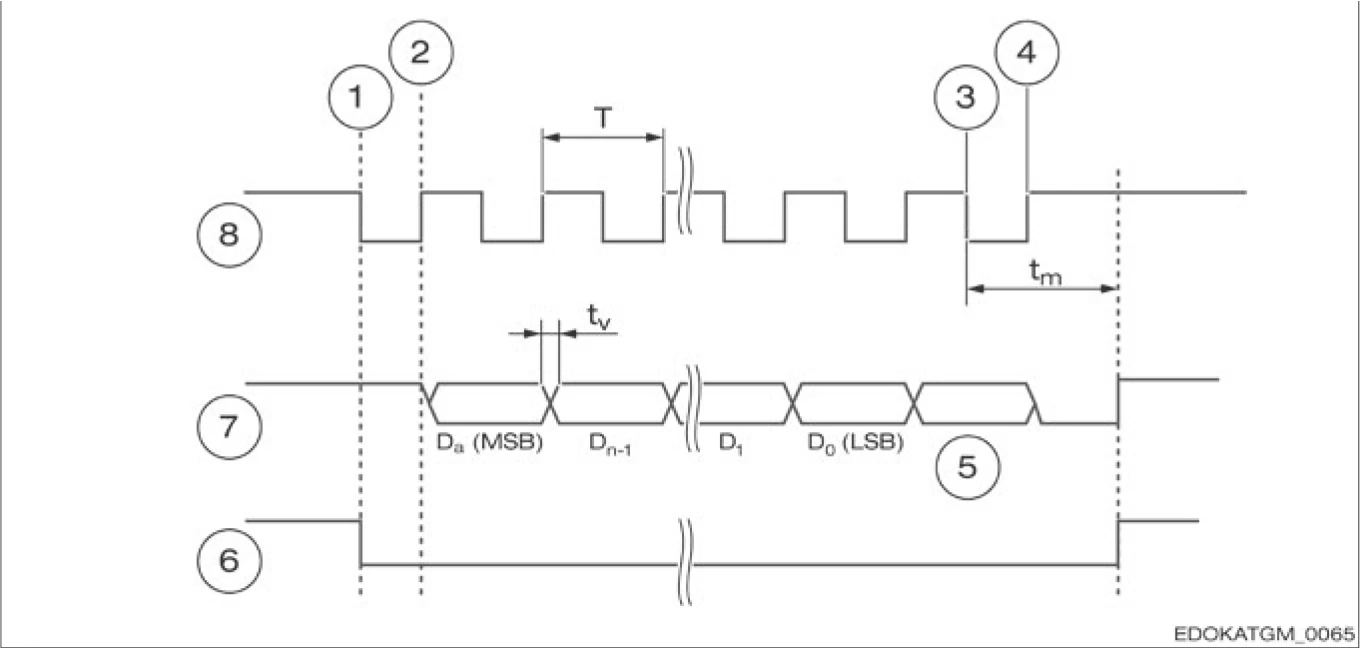
SSI signal timing diagram
Synchronous-Serial Interface with Analogue Signal (SSI + 1 VSS)
The synchronous-serial interface with analogue signal differs from other absolute interfaces in that it basically consists of an incremental interface and a digital interface. The incremental signal is used to determine the position with high precision. The absolute information is used to determine the position value. The incremental position and the absolute position are determined in different parts of the circuit.
This makes it possible to compare the two signals more consistently. Due to the redundant processing of the signals, the operational reliability of the system is significantly increased.

Signal waveform of the synchronous-serial interface with analogue signal, connection between the SSI values and the analogue signals

Illustration for 11-bit multi-turn and 2-bit single-turn, in the case of 4 quadrant evaluation
Track A, Track B and SSI value (11-bit multi-turn, 2-bit single-turn, 4 quadrants/period)
The sine and cosine waves appear in the same period, and the single-turn value is always 0. In the controller, the last two bits are truncated, only multi-turn is counted, and the high-resolution single-turn component is interpolated.
A parameter list for specific controllers is available on request.