7.2.9 Guide Rail Length and Hole Spacing
| Size | L4 | L5 and L10 | Guide rail length L3 … | … max. |
|---|---|---|---|---|
| 5 | 15 | 5 | 25, 40, 55, 70 … | —* |
| 7 | 15 | 5 | 40, 55, 70, 85 … | …1005 |
| 9 | 20 | 7.5 | 55, 75, 95, 115 … | …1000 |
| 12 | 25 | 10 | 70, 95, 120, 145 … | …1000 |
| 15 | 40 | 15 | 70, 110, 150, 190 … | … 995 |
| 14 | 30 | 10 | 80, 110, 140, 170 … | … 985 |
| 18 | 30 | 10 | 80, 110, 140, 170 … | … 985 |
| 24 | 40 | 15 | 110, 150, 190, 230 … | … 995 |
| 42 | 40 | 15 | 110, 150, 190, 230 … | … 990 |
* Maximum rail length for size 5 follows the original SCHNEEBERGER Size 5 brochure; please confirm with the manufacturer.
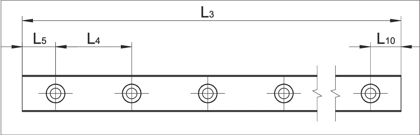
Guide rail length and hole spacing diagram
L3 = Standard rail lengths (mm)
L4, L5, L10 = Standard hole spacings (mm)
Calculating Non-Standard Rail Lengths
Individual rail lengths can be calculated with the following formula (up to a maximum rail length according to the above table):
L3 = (n-1) • L4 + L5 + L10
| L3 | = Rail length (mm) |
|---|---|
| L4, L5, L10 | = Individual hole spacing (mm) |
| L4 | = Standard hole spacing (mm) |
| n | = Number of attachment holes |
Position Tolerance of Attachment Holes and Rail Length Tolerance
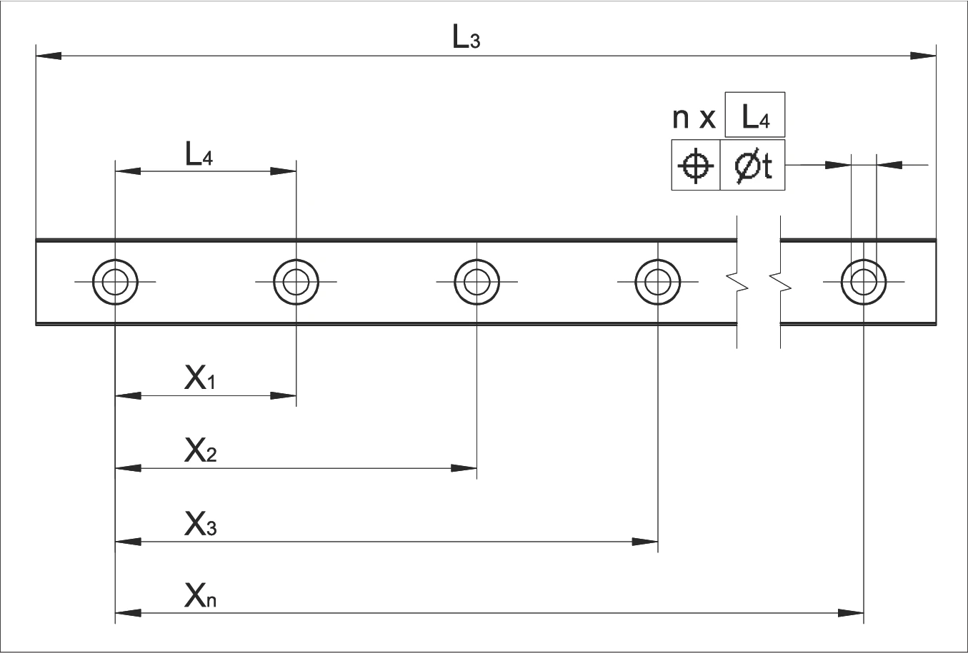
Position tolerance measurement diagram
L3 = Rail length (mm)
L4 = Hole spacing (mm)
n = Number of attachment holes
t = Position tolerance (mm)
| L3 ≤ 300 mm | L3 > 300 mm | |
|---|---|---|
| Position tolerance t of attachment hole | 0.3 | 0.001 • Xn |
| Tolerance of rail length L3 | ±0.3 | ±0.001 • L3 |