5.5.1 Lateral Locating Surfaces
To simplify installation and achieve precise alignment of MONORAIL BZ guide rails, the locating surfaces of the guide rails and carriages should be equipped with lateral locating surfaces. In this way, higher lateral forces can be transmitted to the carriage and/or compressive forces to the guide rail. See Section 5.4 - Fastening Guide Rails and Section 4.13 - Fastening Carriages for permissible lateral forces without locating surfaces. Compliance with the following locating surface height specifications ensures safe force absorption and sufficient clearance for the carriage. The carriage and guide rail have chamfers at the locating surface edges, which means the connecting structure can be designed without relief grooves. The specified fillet radii are maximum values that ensure proper seating of the carriage and guide rail against the locating surfaces.

Connecting Structure Design
Parameter Description
- r1 - Fillet radius at guide rail edge
- r2 - Fillet radius at carriage edge
- H1 - Locating height of guide rail
- H2 - Locating height of carriage
- A1 - Width at guide rail system edge
Technical Specifications
| Model | Size | A1* | H1_min* | H1_max | H2_min* | r1_max | r2_max |
|---|---|---|---|---|---|---|---|
| BZ | 25 | 3.0 | 38.5 | 40 | 4.5 | 0.8 | 1.1 |
| 35 | 5.0 | 54.5 | 56.5 | 6 | 1.3 | 1.3 |
Note
For smaller A1 values, the maximum vertical load on the carriage is reduced. When not using locating rings, the screw layout is critical.
5.5.2 Installation Methods
When selecting the appropriate installation method and determining the number and arrangement of lateral locating surfaces for the BZ system, different criteria must be considered. These include:
- Load
- Required accuracy
- Assembly effort
- Specific installation conditions
For detailed information, see Section 4.14 - Connecting Structure Configuration. The following describes some typical installation methods that differ in the number and orientation of locating surfaces, transmissible lateral forces, and installation complexity, and should serve as design aids:
1. Without Locating Surfaces

Without Locating Surfaces
Features:
- Very simple locating surface configuration
- High assembly effort
- Less force absorbed from the side, force transmitted through friction locking
2. Guide Rail and Carriage with Reference Edge for BZ Guide Rail
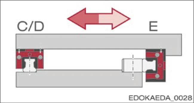
Guide Rail and Carriage with Reference Edge for BZ Guide Rail
Features:
- Carriage on BZ guide rail with lateral fixation
- Simple locating surface configuration
- Minimal assembly effort
- Suitable for high lateral forces from one direction, e.g., suspended installation
- Reference edge on both guide rail and carriage side
3. Guide Rail and Carriage Side with Reference Edge (Fastened from Above)
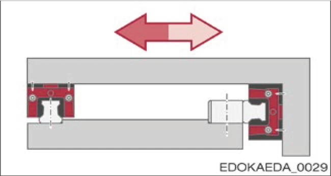
Guide Rail and Carriage Side with Reference Edge, Fastened from Above
Features:
- Carriage on BZ guide rail fastened from above
- Complex slideway configuration
- Simple installation
- Suitable for high lateral forces from one direction, e.g., suspended installation
4. Dual Guide Rail and Carriage Side with Reference Edge

Dual Guide Rail and Carriage Side with Reference Edge, One Guide Rail and Its Carriage Also with Lateral Fixation
Features:
- Simple installation
- Suitable for high compressive forces and high lateral forces from both directions, e.g., horizontal axis
5.5.3 Geometric and Positional Accuracy of Supporting Surfaces, Connection Dimensions
The advantages of SCHNEEBERGER MONORAIL BZ guide rails are best utilized when installed on rigid structures with high geometric accuracy. Inaccuracies in the supporting surfaces are partially compensated by the elastic deformation of the guide rails, but due to these inaccuracies, there may be adverse effects on overall accuracy, running behavior, thrust, and service life.
For MONORAIL BZ, the same specifications as for MONORAIL apply. In Section 4.14 - Connecting Structure Configuration, the following permissible values are defined:
- Lateral height deviation
- Longitudinal height deviation
- Parallelism tolerance of locating surfaces
- Flatness of locating surfaces
The surface quality of the supporting surfaces has no direct effect on the function and running behavior of the guide rails, but does affect static accuracy. The carriage and guide rail are pressed against the locating surfaces with high force through screw connections. To prevent settling behavior of the connection, a high surface contact rate is required. This is achieved through a high level of surface quality. A mean surface roughness of Ra 0.4 to 1.6 μm is recommended for supporting and locating surfaces.

Connection Dimensions for BZ Guide Rail
Connection Dimension Parameters
- L3 - Guide rail length
- L4 - Fixing hole spacing
- L10 - End fixing hole spacing
- L12 - Rack protrusion length
- B4 - Rack protrusion (half guide rail width)
- β - Helix angle
Important Notes
Numerical values for connection dimensions can be found in the MONORAIL and AMS product catalogs.
Note: High-precision geometric shape and positional accuracy of supporting and locating surfaces are critical for achieving optimal system performance, accuracy, and service life.