6.4.1 Arrangement of Measuring System and Reading Head
Reading Head Position and Locating Side
The AMS reading head can be configured in four positions on the carriage. This supports flexible adaptation of the measuring system to the structural design.
The configuration requires the following steps:
- Determine the locating side of the guide rail
- Determine the side of the optical scale
- All combinations are possible here. The respective descriptions are as follows:


- Determine the locating side of the carriage relative to the guide rail
- Carriage locating side:


- The reading head position can be determined by the previous steps and the need to position the reading head on the optical scale side.
- Housing position:
Housing position
Configuration of the Measuring System
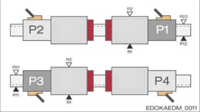
SCHNEEBERGER recommends positioning the reading head between the carriages on the outside of the guide rail. This has the following advantages:
- No additional installation space or additional guide rail length is required to accommodate the housing and reading head
- The reading head is in a protected position between the carriages
- Usually the reading head is easily accessible for maintenance

Fig. 6.xx - Reading head position with multiple carriages
In addition, depending on the installation direction of the axis, the following recommendations should be considered.
Horizontal Axis
The guide rails are placed horizontally next to each other, vertically or rotated 180°. The general recommendation to configure the reading head between the carriages applies here. As long as the machine slide covers cover the guide rail and reading head area, and the machine setup prevents dirt or chip accumulation from depositing next to the guide rails, the reading head is well protected in all cases. When used in dirty working environments and with coolants, additional protective measures are required.
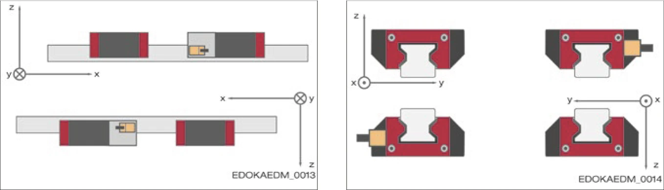
Fig. 6.xx - Reading head configuration for horizontal axis
Vertical Axis
The optimal position is suspended below the upper carriage as shown. Falling dirt particles and chips cannot deposit on the reading head. The lubrication supply is ensured by the lubrication connection on the upper carriage.

Fig. 6.xx - Reading head configuration for vertical axis
Horizontal Axis with Wall-Mounted Assembly
The guide rails are arranged one above the other and rotated 90°. The optimal position of the reading head, depending on the accessibility of the axis, is on the underside of the bottom guide rail (as long as no chip dirt accumulates in this area), or on the underside of the top guide rail. This recommendation also applies to inclined bed axes, such as axes mounted rotated around the longitudinal axis.

Fig. 6.xx - Reading head configuration for wall-mounted horizontal axis; rotated 90° around the longitudinal axis or inclined, e.g., 45° around the longitudinal axis
For more information on guide rail configuration, installation direction and lubrication, please refer to Section 4.8 - Guide Rail Configuration and Section 4.9 - Guide Rail System Installation Methods.
6.4.2 Cabling and Connection to Controller Reading Head Interface
Depending on the type, the AMS measuring system can be provided with different mechanical interfaces, also see SCHNEEBERGER MONORAIL and AMS product catalog. In principle, three different connector variants are available:
- A: Type S
- B: Type R
- C: Type M
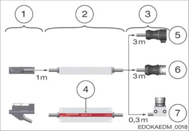
Fig. 6.xx - AMS reading head assembly overview
SCHNEEBERGER recommends using the Type M connector as it can be mounted directly on the machine near the cable carrier through the mounting holes in the mounting bracket. From here, for AMSA and AMSD, the KAO 13 extension cable can be used to continue the connection to the controller connection point.
For an overview of interfaces, extension and connection cables, please refer to the SCHNEEBERGER MONORAIL and AMS product catalog.
As a special implementation, the reading head interface can also be provided with a 0.17m long connecting cable between the reading head and electronics box.
Electronics Box
The electronics box of the reading head should be installed in an easily accessible position for maintenance. There is an LED here for displaying the operating status. Otherwise, it is important to ensure that the cables going in and out of the box are tensioned after laying and have a minimum bending radius (see below).
Cable
When laying measuring system cables, the following points must be observed:
- A 12-pin cable with a minimum cross-section of [4 x (2 x 0.14) + (2 x (2 x 0.5)] mm2 should be used as extension and connection cable between the measuring system and the controller.
- Maximum cable lengths are:
| Signal Type | Max. Cable Length |
|---|---|
| Analog | 30 m |
| Digital | 50 m |
| Absolute | 30 m |
- When using AMS with analog signals and interpolation and digitizing electronics SMEa, the specified cable lengths also apply, meaning max. 30 m between measuring system and SMEa, max. 50 m between SMEa and controller.
- For cable conduits, observe the mounting bracket dimensions or connector diameter (Ø = 28 mm) in the catalog.
- Do not route cables next to interference sources, such as magnetic fields from power supplies, mains power lines, motors, valves, relays and their feeds. Sufficient distance from interference cables can be achieved by observing the following:
- Distance of 0.1 m
- When using metal cable conduits, a grounded partition wall is required
- Maintain at least 0.2 m distance from storage chokes in switching mode power supplies
- Separate hydraulic hoses and cables.
- Route the reading head cable as statically as possible, e.g., do not route in cable carriers. Use extension cables for cable carriers.
- Do not use conduits with sharp edges.
- Route cables without any tensile load.
- Observe the bending radius of the cable:
- Connect the housings of the measuring system and drive controller to the ground of the drive controller through the machine body and/or control cabinet.
- Connect the cable shielding of the connection cable directly to the drive controller, with the connector housing covering a large surface area, and with the lowest possible inductance.
- Avoid electrical contact between connectors (plugs) and other metal parts when there are connectors in the wiring path.
- To prevent grounding through metal housings, only use transmission lines with plastic-covered metal connectors.
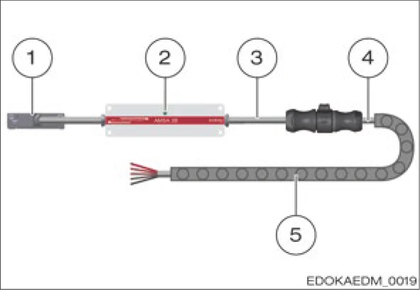
Fig. 6.xx - Reading head interface with cable carrier
| Cable Diameter | Permissible Bending Radius | |
|---|---|---|
| Alternating Bending | Single Bending | |
| 6 mm | > 75 mm | > 20 mm |
| 8 mm | > 100 mm | > 40 mm |
Shielding
The cables of the AMS measuring system are equipped as standard with shielding against electromagnetic interference fields. The shielding in the connection cable is connected to the controller through the connector housing. In addition to cable shielding, the metal housings of the measuring system and drive controller also act as shielding. These housings must exhibit exactly the same potential. They must be connected to the protective ground of the drive controller through the machine body or control cabinet. The cross-section of the equipotential bonding conductor must be at least 6 mm2 (Cu).
Note
Accessibility of Measuring System After Installation
For axes that are difficult to access, it is recommended to provide inspection openings on the machine to easily perform maintenance work on the measuring system. This way, the reading head as well as the connections of the reading head cable and extension cable should be easily accessible.