4.8.1 Principles
Requirements for accuracy class, surface quality, and short machining times are constantly increasing. This is why linear guideways in modern mechanical structures are increasingly determined by the permissible elastic deformation.
Therefore, the following stages are set for dimensioning roller guideways:
- Determining external forces and moments
- Distributing forces and moments to individual carriages
- Determining preload and deformation
- Calculating service life
- Calculating static reliability factor
Service life may be limited by material fatigue or damage to running surfaces caused by environmental influences.
Rolling surfaces cause material fatigue, which damages tracks and rolling elements (pitting). If the forces on the rolling contact surfaces are known, the fatigue service life can be calculated according to DIN IS 281 or DIN 636. Wear on running surfaces depends particularly on lubrication, dirt, surface pressure, and the magnitude of relative motion of the loaded surfaces.
The calculated service life may be shortened by additional failure risks or other aspects, which will void the warranty.

Legend for External Forces and Moments
The following sections explain how to calculate fatigue service life. Due to indeterminable factors, there is no standard procedure for calculating wear life.
4.8.2 Calculating Service Life
Determining External Forces and Moments
The external forces acting on the guideway system are determined by force components Fax, Fay, and Faz, and force application point coordinates Xa, Ya, and Za. Mass m with acceleration components ax, ay, and az produces inertia forces Fmx, Fmy, and Fmz, which act at center of gravity coordinates Xm, Ym, and Zm, thus loading the guideway system.
Forces ΣFy, ΣFz acting perpendicular to the worktable longitudinal axis are borne by the individual carriages and must therefore be distributed to the individual carriages according to the number and position of carriages.
In addition, other external moments Max, May, and Maz may also have an effect. These external moments likewise need to be distributed to the individual MONORAIL carriages.
Distributing Forces and Moments to Individual MONORAIL Carriages
To calculate the lateral force Fjy and tension/compression force Fjz on each carriage (j = 1...n), the principles of statics need to be applied. The distribution of forces and moments can be determined based on the geometry and rigidity of the guideway system.
Determining Preload and Deformation
The preload class of SCHNEEBERGER MONORAIL guideways is determined by operating conditions and is related to the accuracy class of the guideway.
External forces acting on MONORAIL cause displacement of the carriage relative to the guide rail. These displacements vary depending on the preload class and the magnitude of the acting forces. Calculation of displacements requires consideration of the rigidity characteristics of the guideway system.
Factors Influencing Service Life Calculation
Factors affecting service life include forces acting on MONORAIL carriages, preload class, lubrication conditions, operating temperature, degree of contamination, and installation accuracy, among others. These factors must be considered through appropriate correction factors in service life calculations.
Dynamic Equivalent Force P
To calculate service life, the dynamic equivalent force Pj for each MONORAIL carriage (j = 1…n) needs to be determined. The dynamic equivalent force is calculated as follows:
In applications where MONORAIL carriages are subjected to varying loads, when the force exceeds 3 times the preload force, a different calculation method is required. The following diagram illustrates the varying load situation:
The dynamic equivalent force Pj can then be approximated using the following formula:
If force P is not constant, the dynamic equivalent force Pj under staged loading can be calculated as follows:
Dynamic Load Capacity C
Load capacity data for roller guideways is based on principles specified in DIN ISO 14728-2. Dynamic load capacity C is the load at which 90% of a group of identical guideway systems can achieve or exceed the rated travel distance of 100 km before fatigue damage (pitting) occurs under the same operating conditions.
Comparison of Load Capacity
Other manufacturers typically specify their load capacity based on a travel distance of 50 km. To compare with SCHNEEBERGER's load capacity, the following conversion formula can be used:
Event Probability
According to DIN ISO standards, the load capacity of rolling contact bearings is specified for an event probability (reliability) of 90%. This means that 90% of a group of identical guideway systems can achieve or exceed the calculated rated life. For higher reliability requirements, the correction factor a1 can be used:
| Event Probability (%) | 90 | 95 | 96 | 97 | 98 | 99 |
|---|---|---|---|---|---|---|
| a1 | 1 | 0.62 | 0.53 | 0.44 | 0.33 | 0.21 |
Service Life Calculation
For equivalent force P (N) and dynamic load capacity C (N), the nominal calculated life Lnom can be calculated as follows:
Life can also be expressed in operating hours. For this, the average speed and usage factor need to be considered:
Note
For short stroke applications with strokes less than or equal to twice the rolling element diameter, the calculated service life needs to be reduced.
4.8.3 Calculating S₀
Calculating Static Reliability Factor S₀
The static reliability factor S₀ is a safety measure against impermissible permanent deformation of rolling elements and tracks, defined as the ratio of static load capacity C₀ to static equivalent force P₀.
For P₀, the actual forces acting on the rolling contact surfaces must be considered. The determining factor for rolling contact surface deformation is the highest amplitude, even if it occurs only for a very short time. Based on requirements and operating conditions, we recommend observing the following minimum values for static reliability factor S₀:
| Operating Conditions | S₀ |
|---|---|
| Suspended arrangement, applications with high risk potential | ≥ 12 |
| High dynamic stress, high impact loads and vibrations | 8 - 12 |
| Normal machine and equipment design, not all load parameters fully known, moderate alternating loads and vibrations | 5 - 8 |
| All load data fully known, uniform loads and low vibrations | 3 - 5 |
4.8.4 Calculation Program
MONORAIL Dimensioning Calculation Program
Manual calculation of service life, reliability factors, and especially displacements under combined loads is very complex and can only be used for simple applications. Therefore, SCHNEEBERGER offers calculation services using computer programs.
Purpose and Use of MONORAIL Calculation Program
The computer-aided calculation program for MONORAIL dimensioning can determine the following:
- Required MONORAIL size
- Optimal preload
- Static reliability factor
- Rated service life
- Deflection of the working point under load in a given MONORAIL system
The calculation takes into account the true nonlinear rigidity of individual MONORAIL carriages, as well as the interaction between carriages resulting from different rigidity under tension, compression, and lateral loads. Additional deformation due to thermal expansion and elastic deformation of machine structures is not considered.
Required Data
As a design example, complete data is required, as shown in the machine drawing and data table on the next page:
- Guideway geometry, including number of carriages and guide rails, longitudinal and lateral carriage spacing
- Position of axes in space and distances between axes (distance between reference points of adjacent axes)
- Mass of all calculated machine axes and workpieces
- Position of mass center of gravity
- Position of drive elements relative to the corresponding axis reference point
- Load point position (application point of forces and moments)
- Maximum stroke of all calculated axes
- Maximum speed and acceleration of axes
In addition, for different load situations:
- Collective load, including speed, acceleration, travel distance and time percentage, and magnitude and direction of forces and moments applied at the working point according to the corresponding load situation
All geometric dimensions are related to the corresponding axis center (see drawing). The naming of axes in the Cartesian coordinate system can be selected as needed.
For a large number of typical machines and designs, SCHNEEBERGER can provide machine sketches and data tables. For more information, please contact your SCHNEEBERGER representative.
4.8.5 Sample Data Sheet
Sample Data Sheet for X-Y Work Table
Basic Data
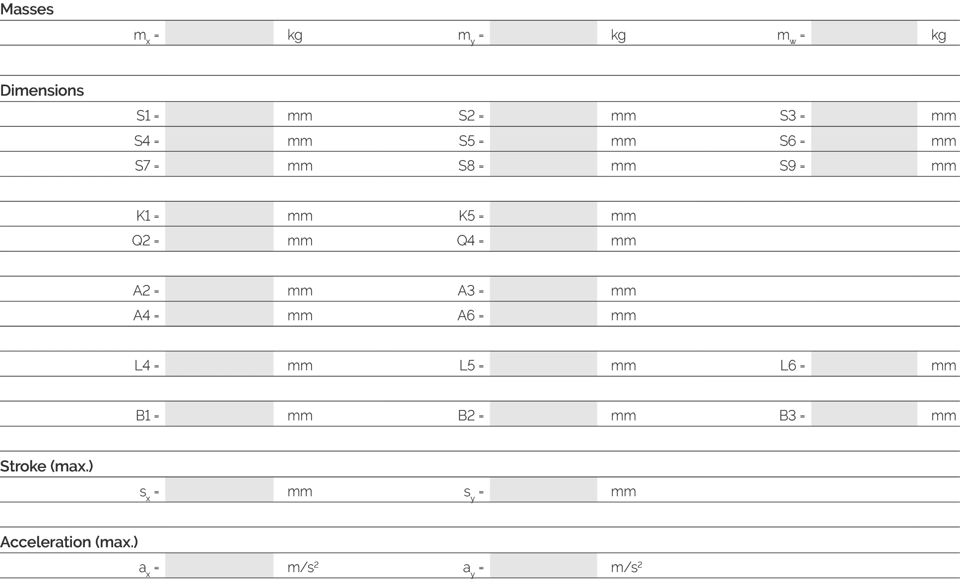
Dimensions
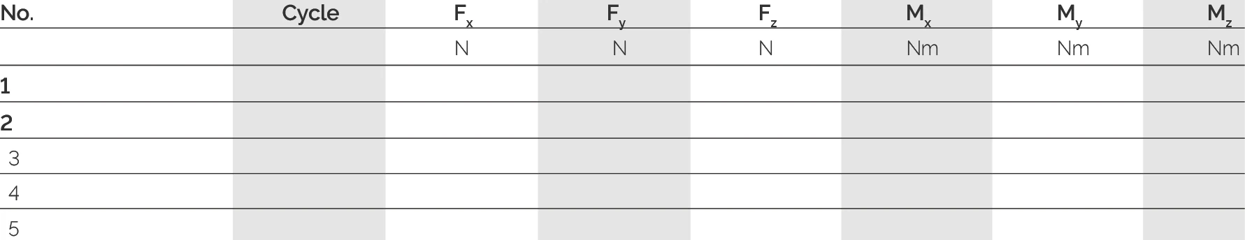
Combined Forces: Forces and Moments

Combined Forces: Distance/Time Ratio
| Parameter | Condition 1 | Condition 2 | Condition 3 | Unit |
|---|---|---|---|---|
| Time Ratio | 40 | 30 | 30 | % |
| Travel Distance | 200 | 150 | 100 | mm |
| Speed v | 40 | 50 | 60 | m/min |
Note: This data table is an example. In actual applications, complete parameter data needs to be filled in according to specific machine configuration and load conditions. SCHNEEBERGER can assist with detailed calculations and verification.
4.8.6 Sample Machine Drawing
Sample Machine Drawing for X-Y Work Table
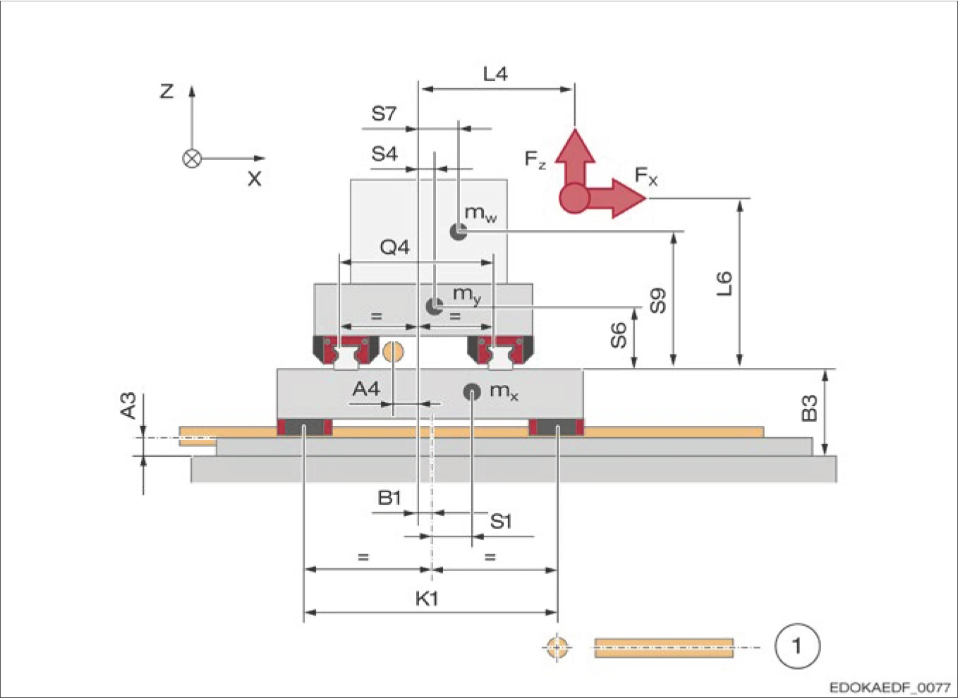
Sample machine drawing for X-Y work table
1 Ball screw
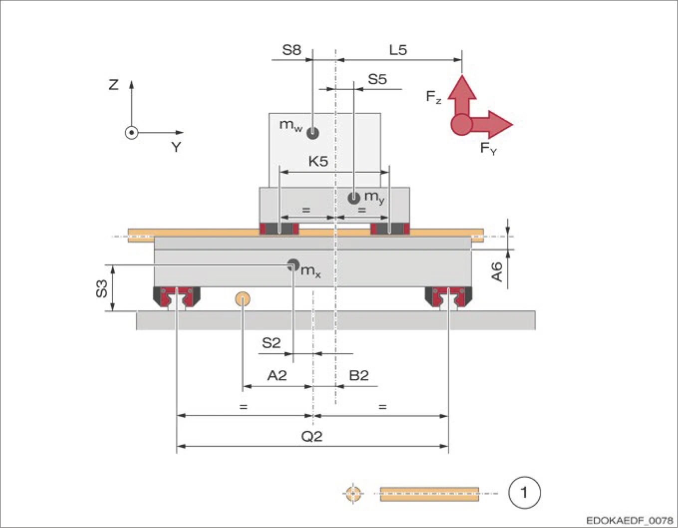
Sample machine drawing for X-Y work table
1 Ball screw
Description: This machine drawing shows a typical MONORAIL guideway configuration for an X-Y work table, including carriage positions, guide rail layout, drive system, and structural design. These drawings can serve as reference examples for the data required by the MONORAIL calculation program.