Positioning Hole
To make alignment of the outer ring easier, the AXDR-ES design series is provided with a positioning hole.
Positioning Hole Location
In the figure below, the cylindrical counterbore is located at the top of the outer ring. The pitch for each bearing size is listed in the "Positioning hole" table of the product data sheet.
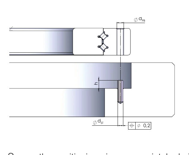
(Click the image to enlarge)
Positioning Hole Design
During assembly, secure the positioning pin properly, or remove it after assembly (for example using a threaded rod). The positioning pin must be reliably prevented from falling out during operation.
For positioning pins left in the bearing, the pin height must be at least 4 mm; from size 580 onwards, the pin height must be at least 6 mm. The maximum pin height is given in the table below.
Positioning Hole Dimension Table
- h: Pin height (max.) [mm]
- dPB: Pin diameter [mm]
- dST: Positioning hole diameter (min.) [mm]
| Designation | h [mm] | dPB [mm] | dST [mm] |
|---|---|---|---|
| AXDR 50 | - | - | - |
| AXDR 80 | 10 | 4 | 5 |
| AXDR 100 | 10 | 4 | 5 |
| AXDR 120 | 15 | 4 | 5 |
| AXDR 150 | 15 | 4 | 5 |
| AXDR 160 | 17.5 | 4 | 5 |
| AXDR 180 | 20 | 4 | 5 |
| AXDR 200 | 20 | 4 | 5 |
| AXDR 210 | 20 | 4 | 5 |
| AXDR 260 | 25 | 4 | 5 |
| AXDR 325 | 25 | 4 | 5 |
| AXDR 350 | 25 | 4 | 5 |
| AXDR 395 | 25 | 4 | 5 |
| AXDR 460 | 25 | 4 | 5 |
| AXDR 580 | 30 | 6 | 8 |
| AXDR 650 | 30 | 8 | 10 |
Data source: official AXDR_ENG catalogue (2026-01), p.20 "Positioning hole" table.