Series Overview
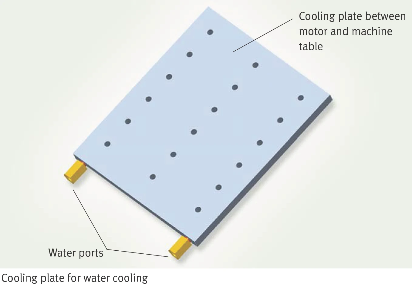
L1C is a water-cooled linear motor with an installation height of 53.5 mm (without cooling plate) / 65.5 mm (with cooling plate) / 66.5 mm (cooling plate + thermal insulation). Compared to L1B, it delivers higher continuous force at the same power dissipation. Cooling options include cooling plate and machine tool thermal insulation.
The L1C series is available in 5 widths (50 / 75 / 100 / 125 / 150 mm) and 4 lengths (100 / 200 / 300 / 400 mm), giving 20 model combinations.
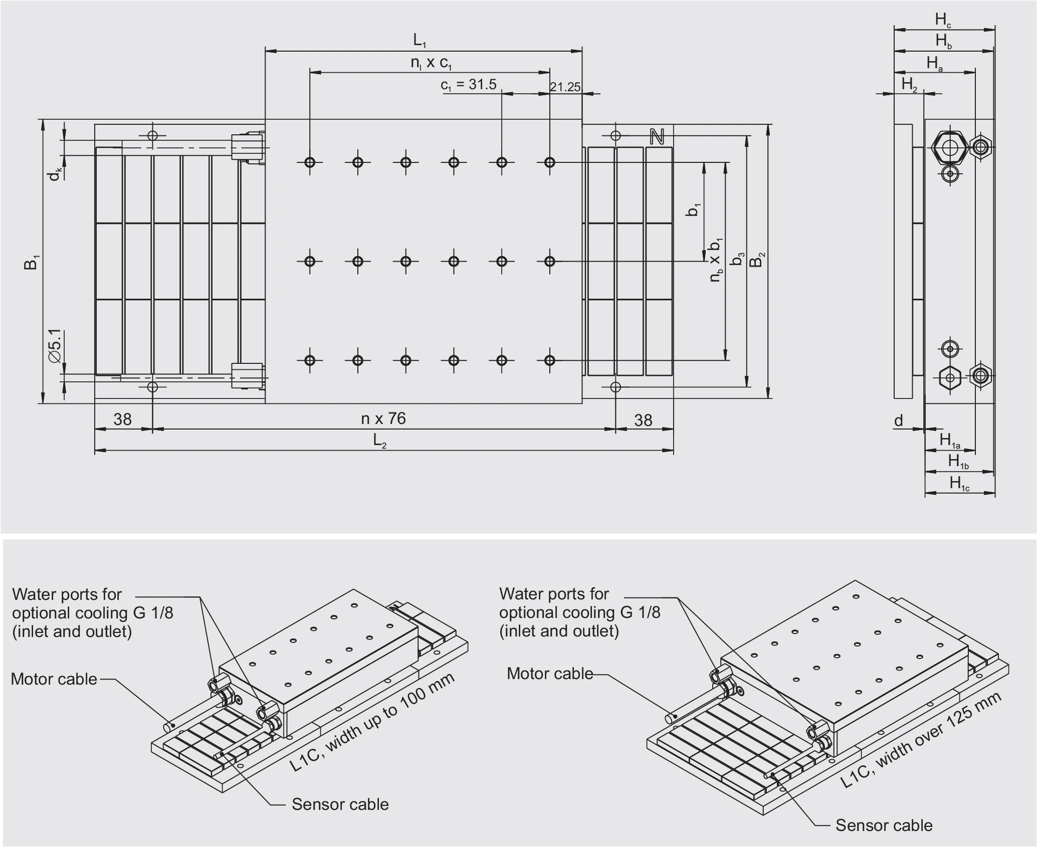
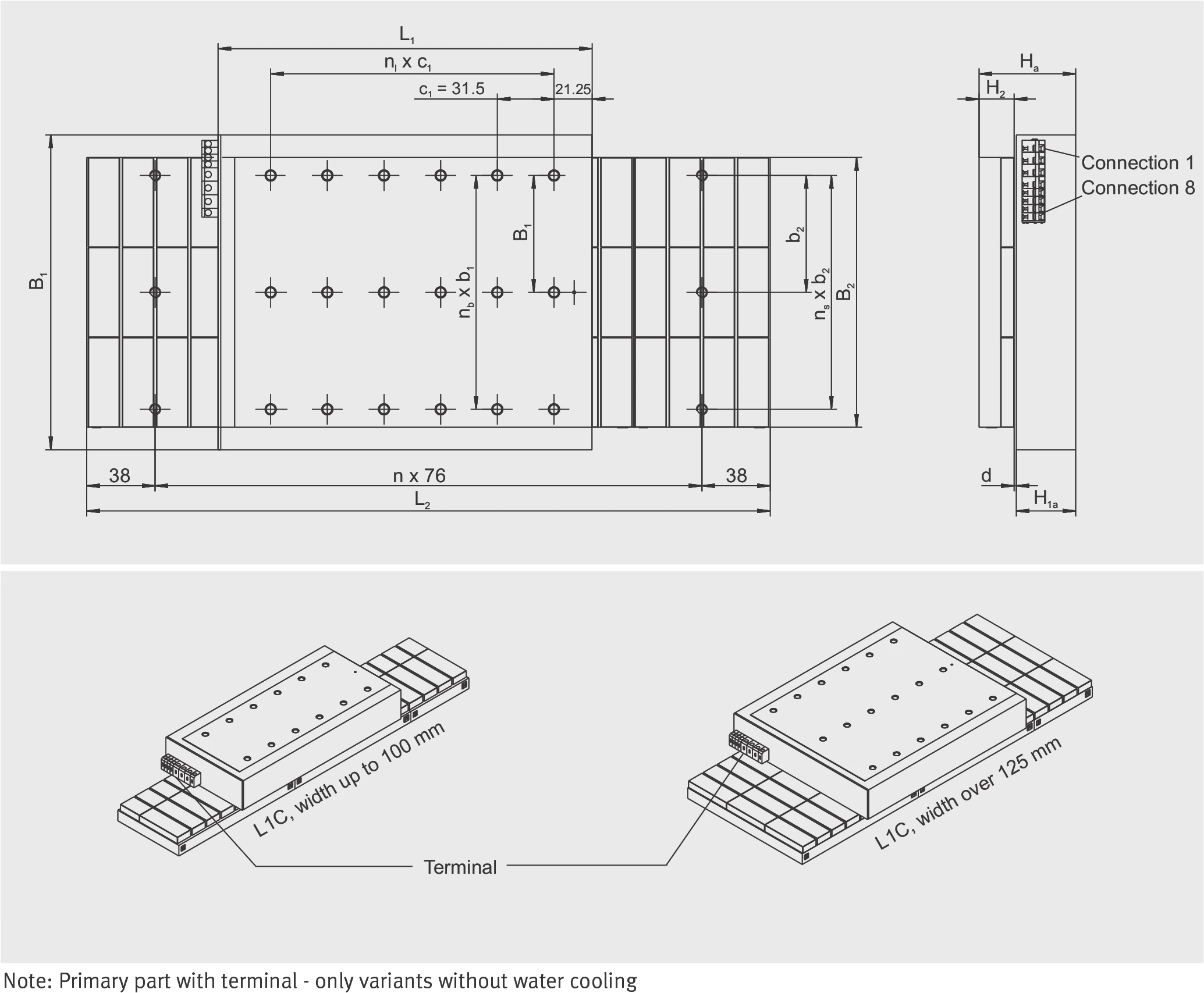
Dimensional Drawing
Cable Connection
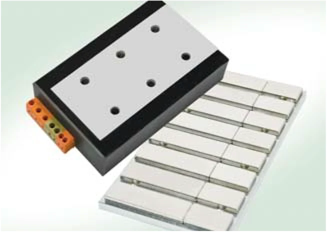
Terminal
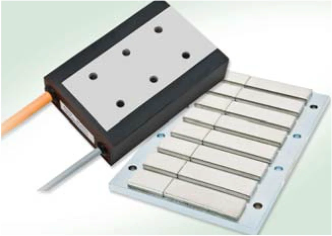
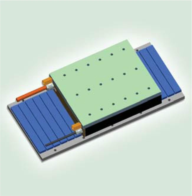
Cooling Components
L1C-3P-100-B
Technical Data I — Mechanical Parameters
| Parameter | Symbol | Unit | 100-50 | 100-75 | 100-100 | 100-125 | 100-150 |
|---|---|---|---|---|---|---|---|
| Primary Part | |||||||
| Length | L1 | mm | 113 | 113 | 113 | 113 | 113 |
| Width | B1 | mm | 82 | 107 | 132 | 157 | 182 |
| Height (w/o cooling plate / with cooling plate) | H1a/H1b | mm | 33/45 | 33/45 | 33/45 | 33/45 | 33/45 |
| Height (cooling plate + insulation) | H1c | mm | 46 | 46 | 46 | 46 | 46 |
| Mass (w/o cooling plate / with cooling plate) | m1a/m1b | kg | 1.5/1.8 | 2.1/2.5 | 2.6/3.1 | 3.2/3.8 | 3.8/4.5 |
| M6 threaded holes (L × W) | — | — | 3 × 2 | 3 × 2 | 3 × 2 | 3 × 3 | 3 × 3 |
| M6 hole pitch / length direction | nl × c1 | mm | 2× 31.5 | 2× 31.5 | 2× 31.5 | 2× 31.5 | 2× 31.5 |
| M6 hole pitch / width direction | nb × b1 | mm | 1× 30 | 1× 55 | 1× 80 | 2× 52.5 | 2× 65 |
| Motor cable diameter | dK | mm | 7.3 | 7.3 | 7.3 | 7.3 | 7.3 |
| Secondary Part — Through-hole type (variant 2) | |||||||
| Width | B2 | mm | 80 | 110 | 130 | 160 | 180 |
| Mass (length 76 / 152) | m2 | kg/pc | 0.78/1.56 | 1.11/2.22 | 1.36/2.72 | 1.68/3.36 | 1.94/3.88 |
| Height | H2 | mm | 19.5 | 19.5 | 19.5 | 19.5 | 19.5 |
| M6 ISO 4762 through-hole spacing | b3 | mm | 65 | 90 | 115 | 140 | 165 |
| Secondary Part — Threaded hole type (variant 1) | |||||||
| Width | B2 | mm | 50 | 80 | 100 | 130 | 150 |
| Mass (length 76 / 152) | m2 | kg/pc | 0.58/1.16 | 0.90/1.80 | 1.16/2.32 | 1.47/2.94 | 1.72/3.44 |
| Height | H2 | mm | 19.5 | 19.5 | 19.5 | 19.5 | 19.5 |
| M6 threaded holes (bottom face) | b2 | mm | 38 | 55 | 80 | 105 | 2 × 65 |
| Installation Dimensions | |||||||
| Total height (without cooling plate) | Ha | mm | 53.5 + 0.1 | 53.5 + 0.1 | 53.5 + 0.1 | 53.5 + 0.1 | 53.5 + 0.1 |
| Total height (with cooling plate) | Hb | mm | 65.5 + 0.1 | 65.5 + 0.1 | 65.5 + 0.1 | 65.5 + 0.1 | 65.5 + 0.1 |
| Total height (cooling plate + insulation) | Hc | mm | 66.5 + 0.1 | 66.5 + 0.1 | 66.5 + 0.1 | 66.5 + 0.1 | 66.5 + 0.1 |
| Mechanical air gap | d | mm | approx. 1 | approx. 1 | approx. 1 | approx. 1 | approx. 1 |
| Maximum width (by variant) | B | mm | 82 | 107/110 | 132 | 157/160 | 182 |
| Secondary part length (76 mm grid) | L2 | mm | L1+stroke | L1+stroke | L1+stroke | L1+stroke | L1+stroke |
| Cable length | LK | mm | ≈ 1000 | ≈ 1000 | ≈ 1000 | ≈ 1000 | ≈ 1000 |
Technical Data II — Electrical Performance
| Parameter | Symbol | Unit | 100-50 | 100-75 | 100-100 | 100-125 | 100-150 |
|---|---|---|---|---|---|---|---|
| Limit force (Iu) | Fu | N | 515 | 768 | 1020 | 1268 | 1515 |
| Peak force — saturated (Ip) | Fp | N | 439 | 656 | 870 | 1082 | 1293 |
| Peak force — linear (Ipl) | Fpl | N | 259 | 387 | 514 | 639 | 763 |
| Continuous force — water-cooled (Icw) | Fcw | N | 249 | 395 | 543 | 691 | 838 |
| Continuous force — uncooled (Ic) | Fc | N | 131 | 196 | 259 | 322 | 387 |
| Power loss at Fp (25 °C) | Plp | W | 528 | 698 | 869 | 1039 | 1209 |
| Power loss at Fpl (25 °C) | Plpl | W | 118 | 156 | 194 | 232 | 270 |
| Power loss at Fcw | Plcw | W | 141 | 211 | 282 | 352 | 423 |
| Power loss at Fc (25 °C) | Plc | W | 30 | 40 | 49 | 59 | 69 |
| Motor constant (25 °C) | km | N/√W | 23.9 | 31.0 | 36.9 | 42.0 | 46.5 |
| Damping constant (short circuit) | kd | N/(m/s) | 571 | 962 | 1362 | 1762 | 2160 |
| Electrical time constant | τel | ms | 8.67 | 9.83 | 10.54 | 11.02 | 11.36 |
| Attraction force | Fa | N | 1174 | 1760 | 2347 | 2934 | 3521 |
| Cogging force (typical) | Fr | N | 12 | 18 | 24 | 30 | 36 |
| Pole pair width | 2τp | mm | 38 | 38 | 38 | 38 | 38 |
| Cooling water flow rate | dV/dt | l/min | 0.4 | 0.6 | 0.8 | 1.0 | 1.2 |
| Cooling water temperature rise | Δθ | K | 5.0 | 5.0 | 5.0 | 5.0 | 5.0 |
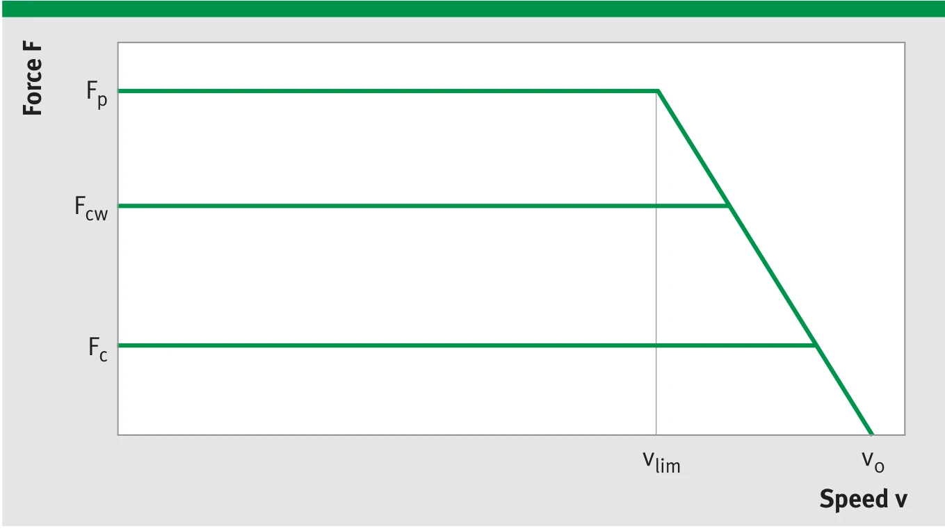
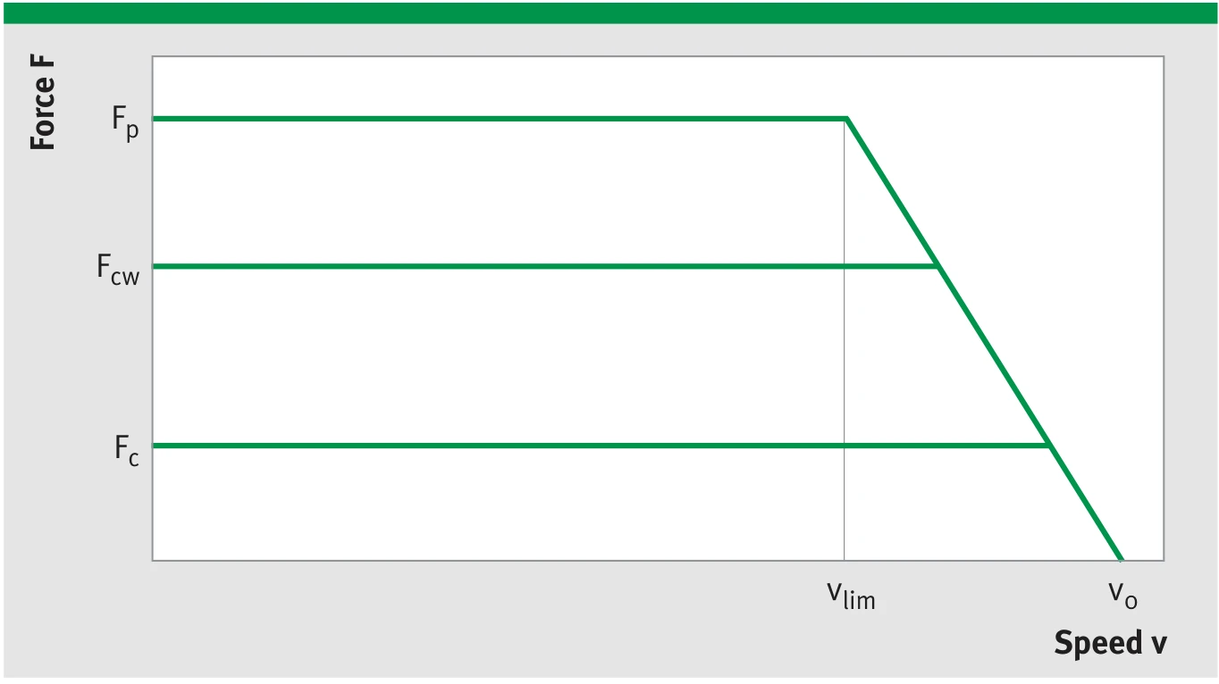
L1C-3P-100-B Force-Speed (F-v) and Force-Current (F-I) characteristic curves
The achievable speed limit depends on operating voltage (UDCL) and current (force). The diagram shows the idealised envelope with the key operating points at peak current (Fp, vlim) and at idle (Fo, v0).
Technical Data III — Winding Data
| Parameter | Symbol | Unit | 100-50 | 100-75 | 100-100 | 100-125 | 100-150 |
|---|---|---|---|---|---|---|---|
| Force constant | kf | N/Arms | 53.7 | 80.2 | 106.5 | 132.5 | 158.2 |
| Back EMF constant (phase-to-phase) | ku | V/(m/s) | 44.0 | 65.6 | 87.1 | 108.4 | 129.4 |
| Limit speed (Ip, UDCL=300 VDC) | vlim | m/s | 3.8 | 2.4 | 1.7 | 1.2 | 0.9 |
| Limit speed (Ip, UDCL=600 VDC) | vlim | m/s | 8.1 | 5.3 | 3.9 | 3.0 | 2.4 |
| Resistance (phase-to-phase, 25 °C) | R25 | Ω | 3.37 | 4.46 | 5.55 | 6.64 | 7.73 |
| Inductance (phase-to-phase) | L | mH | 29.26 | 43.89 | 58.52 | 73.15 | 87.78 |
| Limit current | Iu | Arms | 12.8 | 12.8 | 12.8 | 12.8 | 12.8 |
| Peak current (saturated) | Ip | Arms | 10.2 | 10.2 | 10.2 | 10.2 | 10.2 |
| Peak current (linear) | Ipl | Arms | 4.8 | 4.8 | 4.8 | 4.8 | 4.8 |
| Continuous current (water-cooled) | Icw | Arms | 4.6 | 4.9 | 5.1 | 5.2 | 5.3 |
| Continuous current (uncooled) | Ic | Arms | 2.4 | 2.4 | 2.4 | 2.4 | 2.4 |
| Permissible temperature (at sensor) | θ | °C | 100 | 100 | 100 | 100 | 100 |
| Maximum DC bus voltage | UDCL | V | 600 | 600 | 600 | 600 | 600 |

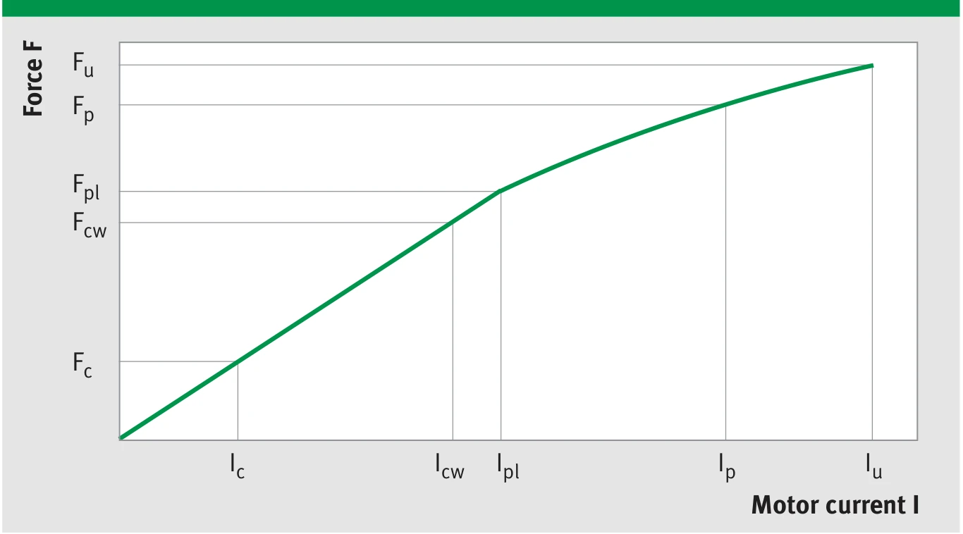
L1C-3P-100-B winding parameter characteristic
Note: The winding variant WM (standard) described above is suitable for moderately dynamic performance requirements. The winding variants WL and WH suitable for lower and higher dynamic performance requirements are available upon request. The integrated temperature sensors do not display the exact winding temperature. Depending on current load, the winding temperature may be up to approx. 30 K higher.
L1C-3P-200-B
Technical Data I — Mechanical Parameters
| Parameter | Symbol | Unit | 200-50 | 200-75 | 200-100 | 200-125 | 200-150 |
|---|---|---|---|---|---|---|---|
| Primary Part | |||||||
| Length | L1 | mm | 208 | 208 | 208 | 208 | 208 |
| Width | B1 | mm | 82 | 107 | 132 | 157 | 182 |
| Height (w/o cooling plate / with cooling plate) | H1a/H1b | mm | 33/45 | 33/45 | 33/45 | 33/45 | 33/45 |
| Height (cooling plate + insulation) | H1c | mm | 46 | 46 | 46 | 46 | 46 |
| Mass (w/o cooling plate / with cooling plate) | m1a/m1b | kg | 2.8/3.4 | 3.8/4.5 | 5.0/5.9 | 6.1/7.2 | 7.2/8.4 |
| M6 threaded holes (L × W) | — | — | 6 × 2 | 6 × 2 | 6 × 2 | 6 × 3 | 6 × 3 |
| M6 hole pitch / length direction | nl × c1 | mm | 5× 31.5 | 5× 31.5 | 5× 31.5 | 5× 31.5 | 5× 31.5 |
| M6 hole pitch / width direction | nb × b1 | mm | 1× 30 | 1× 55 | 1× 80 | 2× 52.5 | 2× 65 |
| Motor cable diameter | dK | mm | 10 | 10 | 10 | 10 | 10 |
| Secondary Part — Through-hole type (variant 2) | |||||||
| Width | B2 | mm | 80 | 110 | 130 | 160 | 180 |
| Mass (length 76 / 152) | m2 | kg/pc | 0.78/1.56 | 1.11/2.22 | 1.36/2.72 | 1.68/3.36 | 1.94/3.88 |
| Height | H2 | mm | 19.5 | 19.5 | 19.5 | 19.5 | 19.5 |
| M6 ISO 4762 through-hole spacing | b3 | mm | 65 | 90 | 115 | 140 | 165 |
| Secondary Part — Threaded hole type (variant 1) | |||||||
| Width | B2 | mm | 50 | 80 | 100 | 130 | 150 |
| Mass (length 76 / 152) | m2 | kg/pc | 0.58/1.16 | 0.90/1.80 | 1.16/2.32 | 1.47/2.94 | 1.72/3.44 |
| Height | H2 | mm | 19.5 | 19.5 | 19.5 | 19.5 | 19.5 |
| M6 threaded holes (bottom face) | b2 | mm | 38 | 55 | 80 | 105 | 2 × 65 |
| Installation Dimensions | |||||||
| Total height (without cooling plate) | Ha | mm | 53.5 + 0.1 | 53.5 + 0.1 | 53.5 + 0.1 | 53.5 + 0.1 | 53.5 + 0.1 |
| Total height (with cooling plate) | Hb | mm | 65.5 + 0.1 | 65.5 + 0.1 | 65.5 + 0.1 | 65.5 + 0.1 | 65.5 + 0.1 |
| Total height (cooling plate + insulation) | Hc | mm | 66.5 + 0.1 | 66.5 + 0.1 | 66.5 + 0.1 | 66.5 + 0.1 | 66.5 + 0.1 |
| Mechanical air gap | d | mm | approx. 1 | approx. 1 | approx. 1 | approx. 1 | approx. 1 |
| Maximum width (by variant) | B | mm | 82 | 107/110 | 132 | 157/160 | 182 |
| Secondary part length (76 mm grid) | L2 | mm | L1+stroke | L1+stroke | L1+stroke | L1+stroke | L1+stroke |
| Cable length | LK | mm | ≈ 1000 | ≈ 1000 | ≈ 1000 | ≈ 1000 | ≈ 1000 |
Technical Data II — Electrical Performance
| Parameter | Symbol | Unit | 200-50 | 200-75 | 200-100 | 200-125 | 200-150 |
|---|---|---|---|---|---|---|---|
| Limit force (Iu) | Fu | N | 1029 | 1537 | 2039 | 2537 | 3030 |
| Peak force — saturated (Ip) | Fp | N | 878 | 1311 | 1740 | 2165 | 2586 |
| Peak force — linear (Ipl) | Fpl | N | 518 | 774 | 1027 | 1278 | 1526 |
| Continuous force — water-cooled (Icw) | Fcw | N | 488 | 776 | 1067 | 1357 | 1645 |
| Continuous force — uncooled (Ic) | Fc | N | 247 | 366 | 487 | 605 | 724 |
| Power loss at Fp (25 °C) | Plp | W | 1056 | 1396 | 1737 | 2078 | 2418 |
| Power loss at Fpl (25 °C) | Plpl | W | 235 | 311 | 387 | 463 | 539 |
| Power loss at Fcw | Plcw | W | 272 | 407 | 543 | 679 | 815 |
| Power loss at Fc (25 °C) | Plc | W | 53 | 70 | 87 | 104 | 121 |
| Motor constant (25 °C) | km | N/√W | 33.8 | 43.9 | 52.2 | 59.4 | 65.7 |
| Damping constant (short circuit) | kd | N/(m/s) | 1141 | 1924 | 2724 | 3525 | 4319 |
| Electrical time constant | τel | ms | 8.67 | 9.83 | 10.54 | 11.02 | 11.36 |
| Attraction force | Fa | N | 2261 | 3392 | 4523 | 5653 | 6784 |
| Cogging force (typical) | Fr | N | 14 | 20 | 26 | 32 | 38 |
| Pole pair width | 2τp | mm | 38 | 38 | 38 | 38 | 38 |
| Cooling water flow rate | dV/dt | l/min | 0.8 | 1.2 | 1.6 | 1.9 | 2.3 |
| Cooling water temperature rise | Δθ | K | 5.0 | 5.0 | 5.0 | 5.0 | 5.0 |
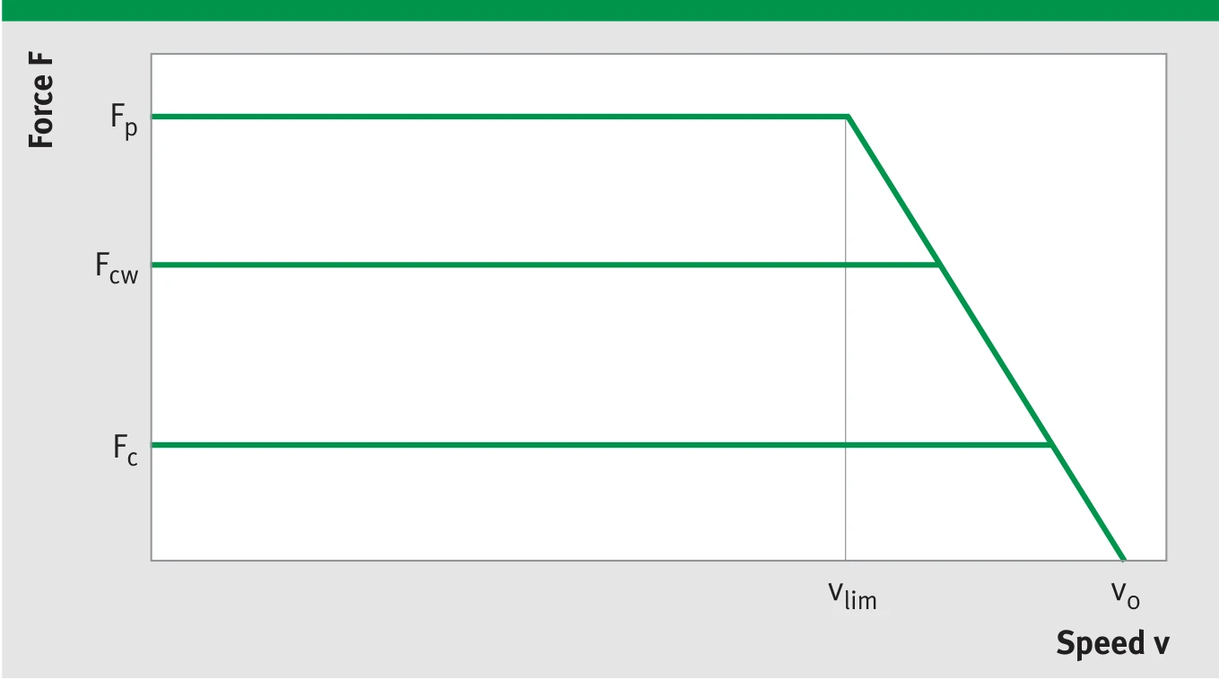
L1C-3P-200-B Force-Speed (F-v) and Force-Current (F-I) characteristic curves
The achievable speed limit depends on operating voltage (UDCL) and current (force). The diagram shows the idealised envelope with the key operating points at peak current (Fp, vlim) and at idle (Fo, v0).
Technical Data III — Winding Data
| Parameter | Symbol | Unit | 200-50 | 200-75 | 200-100 | 200-125 | 200-150 |
|---|---|---|---|---|---|---|---|
| Force constant | kf | N/Arms | 53.7 | 80.2 | 106.5 | 132.5 | 158.2 |
| Back EMF constant (phase-to-phase) | ku | V/(m/s) | 44.0 | 65.6 | 87.1 | 108.4 | 129.4 |
| Limit speed (Ip, UDCL=300 VDC) | vlim | m/s | 3.6 | 2.2 | 1.5 | 1.1 | 0.9 |
| Limit speed (Ip, UDCL=600 VDC) | vlim | m/s | 7.7 | 5.0 | 3.6 | 2.8 | 2.3 |
| Resistance (phase-to-phase, 25 °C) | R25 | Ω | 1.69 | 2.23 | 2.78 | 3.32 | 3.86 |
| Inductance (phase-to-phase) | L | mH | 14.63 | 21.95 | 29.26 | 36.58 | 43.89 |
| Limit current | Iu | Arms | 25.5 | 25.5 | 25.5 | 25.5 | 25.5 |
| Peak current (saturated) | Ip | Arms | 20.4 | 20.4 | 20.4 | 20.4 | 20.4 |
| Peak current (linear) | Ipl | Arms | 9.6 | 9.6 | 9.6 | 9.6 | 9.6 |
| Continuous current (water-cooled) | Icw | Arms | 9.1 | 9.7 | 10.0 | 10.2 | 10.4 |
| Continuous current (uncooled) | Ic | Arms | 4.6 | 4.6 | 4.6 | 4.6 | 4.6 |
| Permissible temperature (at sensor) | θ | °C | 100 | 100 | 100 | 100 | 100 |
| Maximum DC bus voltage | UDCL | V | 600 | 600 | 600 | 600 | 600 |

L1C-3P-200-B winding parameter characteristic
Note: The winding variant WM (standard) described above is suitable for moderately dynamic performance requirements. The winding variants WL and WH suitable for lower and higher dynamic performance requirements are available upon request. The integrated temperature sensors do not display the exact winding temperature. Depending on current load, the winding temperature may be up to approx. 30 K higher.
L1C-3P-300-B
Technical Data I — Mechanical Parameters
| Parameter | Symbol | Unit | 300-50 | 300-75 | 300-100 | 300-125 | 300-150 |
|---|---|---|---|---|---|---|---|
| Primary Part | |||||||
| Length | L1 | mm | 303 | 303 | 303 | 303 | 303 |
| Width | B1 | mm | 82 | 107 | 132 | 157 | 182 |
| Height (w/o cooling plate / with cooling plate) | H1a/H1b | mm | 33/45 | 33/45 | 33/45 | 33/45 | 33/45 |
| Height (cooling plate + insulation) | H1c | mm | 46 | 46 | 46 | 46 | 46 |
| Mass (w/o cooling plate / with cooling plate) | m1a/m1b | kg | 4.1/4.9 | 5.7/6.7 | 7.3/8.6 | 8.9/10.4 | 10.5/12.2 |
| M6 threaded holes (L × W) | — | — | 9 × 2 | 9 × 2 | 9 × 2 | 9 × 3 | 9 × 3 |
| M6 hole pitch / length direction | nl × c1 | mm | 8× 31.5 | 8× 31.5 | 8× 31.5 | 8× 31.5 | 8× 31.5 |
| M6 hole pitch / width direction | nb × b1 | mm | 1× 30 | 1× 55 | 1× 80 | 2× 52.5 | 2× 65 |
| Motor cable diameter | dK | mm | 10 | 10 | 10 | 10 | 10 |
| Secondary Part — Through-hole type (variant 2) | |||||||
| Width | B2 | mm | 80 | 110 | 130 | 160 | 180 |
| Mass (length 76 / 152) | m2 | kg/pc | 0.78/1.56 | 1.11/2.22 | 1.36/2.72 | 1.68/3.36 | 1.94/3.88 |
| Height | H2 | mm | 19.5 | 19.5 | 19.5 | 19.5 | 19.5 |
| M6 ISO 4762 through-hole spacing | b3 | mm | 65 | 90 | 115 | 140 | 165 |
| Secondary Part — Threaded hole type (variant 1) | |||||||
| Width | B2 | mm | 50 | 80 | 100 | 130 | 150 |
| Mass (length 76 / 152) | m2 | kg/pc | 0.58/1.16 | 0.90/1.80 | 1.16/2.32 | 1.47/2.94 | 1.72/3.44 |
| Height | H2 | mm | 19.5 | 19.5 | 19.5 | 19.5 | 19.5 |
| M6 threaded holes (bottom face) | b2 | mm | 38 | 55 | 80 | 105 | 2 × 65 |
| Installation Dimensions | |||||||
| Total height (without cooling plate) | Ha | mm | 53.5 + 0.1 | 53.5 + 0.1 | 53.5 + 0.1 | 53.5 + 0.1 | 53.5 + 0.1 |
| Total height (with cooling plate) | Hb | mm | 65.5 + 0.1 | 65.5 + 0.1 | 65.5 + 0.1 | 65.5 + 0.1 | 65.5 + 0.1 |
| Total height (cooling plate + insulation) | Hc | mm | 66.5 + 0.1 | 66.5 + 0.1 | 66.5 + 0.1 | 66.5 + 0.1 | 66.5 + 0.1 |
| Mechanical air gap | d | mm | approx. 1 | approx. 1 | approx. 1 | approx. 1 | approx. 1 |
| Maximum width (by variant) | B | mm | 82 | 107/110 | 132 | 157/160 | 182 |
| Secondary part length (76 mm grid) | L2 | mm | L1+stroke | L1+stroke | L1+stroke | L1+stroke | L1+stroke |
| Cable length | LK | mm | ≈ 1000 | ≈ 1000 | ≈ 1000 | ≈ 1000 | ≈ 1000 |
Technical Data II — Electrical Performance
| Parameter | Symbol | Unit | 300-50 | 300-75 | 300-100 | 300-125 | 300-150 |
|---|---|---|---|---|---|---|---|
| Limit force (Iu) | Fu | N | 1544 | 2305 | 3059 | 3805 | 4545 |
| Peak force — saturated (Ip) | Fp | N | 1317 | 1967 | 2610 | 3247 | 3878 |
| Peak force — linear (Ipl) | Fpl | N | 778 | 1161 | 1541 | 1917 | 2289 |
| Continuous force — water-cooled (Icw) | Fcw | N | 728 | 1157 | 1590 | 2022 | 2452 |
| Continuous force — uncooled (Ic) | Fc | N | 361 | 540 | 717 | 890 | 1066 |
| Power loss at Fp (25 °C) | Plp | W | 1584 | 2095 | 2606 | 3117 | 3627 |
| Power loss at Fpl (25 °C) | Plpl | W | 353 | 467 | 581 | 695 | 809 |
| Power loss at Fcw | Plcw | W | 402 | 603 | 804 | 1005 | 1207 |
| Power loss at Fc (25 °C) | Plc | W | 76 | 101 | 126 | 150 | 176 |
| Motor constant (25 °C) | km | N/√W | 41.4 | 53.7 | 63.9 | 72.7 | 80.5 |
| Damping constant (short circuit) | kd | N/(m/s) | 1712 | 2886 | 4085 | 5287 | 6479 |
| Electrical time constant | τel | ms | 8.67 | 9.83 | 10.54 | 11.02 | 11.36 |
| Attraction force | Fa | N | 3349 | 5024 | 6698 | 8373 | 10047 |
| Cogging force (typical) | Fr | N | 16 | 22 | 28 | 34 | 36 |
| Pole pair width | 2τp | mm | 38 | 38 | 38 | 38 | 38 |
| Cooling water flow rate | dV/dt | l/min | 1.1 | 1.7 | 2.3 | 2.9 | 3.4 |
| Cooling water temperature rise | Δθ | K | 5.0 | 5.0 | 5.0 | 5.0 | 5.0 |
L1C-3P-300-B Force-Speed (F-v) and Force-Current (F-I) characteristic curves
The achievable speed limit depends on operating voltage (UDCL) and current (force). The diagram shows the idealised envelope with the key operating points at peak current (Fp, vlim) and at idle (Fo, v0).
Technical Data III — Winding Data
| Parameter | Symbol | Unit | 300-50 | 300-75 | 300-100 | 300-125 | 300-150 |
|---|---|---|---|---|---|---|---|
| Force constant | kf | N/Arms | 53.7 | 80.2 | 106.5 | 132.5 | 158.2 |
| Back EMF constant (phase-to-phase) | ku | V/(m/s) | 44.0 | 65.6 | 87.1 | 108.4 | 129.4 |
| Limit speed (Ip, UDCL=300 VDC) | vlim | m/s | 3.6 | 2.2 | 1.5 | 1.1 | 0.9 |
| Limit speed (Ip, UDCL=600 VDC) | vlim | m/s | 7.7 | 5.0 | 3.6 | 2.8 | 2.3 |
| Resistance (phase-to-phase, 25 °C) | R25 | Ω | 1.12 | 1.49 | 1.85 | 2.21 | 2.58 |
| Inductance (phase-to-phase) | L | mH | 9.75 | 14.63 | 19.51 | 24.38 | 29.26 |
| Limit current | Iu | Arms | 38.3 | 38.3 | 38.3 | 38.3 | 38.3 |
| Peak current (saturated) | Ip | Arms | 30.6 | 30.6 | 30.6 | 30.6 | 30.6 |
| Peak current (linear) | Ipl | Arms | 14.5 | 14.5 | 14.5 | 14.5 | 14.5 |
| Continuous current (water-cooled) | Icw | Arms | 13.5 | 14.4 | 14.9 | 15.3 | 15.5 |
| Continuous current (uncooled) | Ic | Arms | 6.7 | 6.7 | 6.7 | 6.7 | 6.7 |
| Permissible temperature (at sensor) | θ | °C | 100 | 100 | 100 | 100 | 100 |
| Maximum DC bus voltage | UDCL | V | 600 | 600 | 600 | 600 | 600 |

L1C-3P-300-B winding parameter characteristic
Note: The winding variant WM (standard) described above is suitable for moderately dynamic performance requirements. The winding variants WL and WH suitable for lower and higher dynamic performance requirements are available upon request. The integrated temperature sensors do not display the exact winding temperature. Depending on current load, the winding temperature may be up to approx. 30 K higher.
L1C-3P-400-B
Technical Data I — Mechanical Parameters
| Parameter | Symbol | Unit | 400-50 | 400-75 | 400-100 | 400-125 | 400-150 |
|---|---|---|---|---|---|---|---|
| Primary Part | |||||||
| Length | L1 | mm | 398 | 398 | 398 | 398 | 398 |
| Width | B1 | mm | 82 | 107 | 132 | 157 | 182 |
| Height (w/o cooling plate / with cooling plate) | H1a/H1b | mm | 33/45 | 33/45 | 33/45 | 33/45 | 33/45 |
| Height (cooling plate + insulation) | H1c | mm | 46 | 46 | 46 | 46 | 46 |
| Mass (w/o cooling plate / with cooling plate) | m1a/m1b | kg | 5.4/6.4 | 7.5/8.8 | 9.6/11.3 | 11.8/13.8 | 13.9/16.2 |
| M6 threaded holes (L × W) | — | — | 12 × 2 | 12 × 2 | 12 × 2 | 12 × 3 | 12 × 3 |
| M6 hole pitch / length direction | nl × c1 | mm | 11× 31.5 | 11× 31.5 | 11× 31.5 | 11× 31.5 | 11× 31.5 |
| M6 hole pitch / width direction | nb × b1 | mm | 1× 30 | 1× 55 | 1× 80 | 2× 52.5 | 2× 65 |
| Motor cable diameter | dK | mm | 11.6 | 11.6 | 11.6 | 11.6 | 11.6 |
| Secondary Part — Through-hole type (variant 2) | |||||||
| Width | B2 | mm | 80 | 110 | 130 | 160 | 180 |
| Mass (length 76 / 152) | m2 | kg/pc | 0.78/1.56 | 1.11/2.22 | 1.36/2.72 | 1.68/3.36 | 1.94/3.88 |
| Height | H2 | mm | 19.5 | 19.5 | 19.5 | 19.5 | 19.5 |
| M6 ISO 4762 through-hole spacing | b3 | mm | 65 | 90 | 115 | 140 | 165 |
| Secondary Part — Threaded hole type (variant 1) | |||||||
| Width | B2 | mm | 50 | 80 | 100 | 130 | 150 |
| Mass (length 76 / 152) | m2 | kg/pc | 0.58/1.16 | 0.90/1.80 | 1.16/2.32 | 1.47/2.94 | 1.72/3.44 |
| Height | H2 | mm | 19.5 | 19.5 | 19.5 | 19.5 | 19.5 |
| M6 threaded holes (bottom face) | b2 | mm | 38 | 55 | 80 | 105 | 2 × 65 |
| Installation Dimensions | |||||||
| Total height (without cooling plate) | Ha | mm | 53.5 + 0.1 | 53.5 + 0.1 | 53.5 + 0.1 | 53.5 + 0.1 | 53.5 + 0.1 |
| Total height (with cooling plate) | Hb | mm | 65.5 + 0.1 | 65.5 + 0.1 | 65.5 + 0.1 | 65.5 + 0.1 | 65.5 + 0.1 |
| Total height (cooling plate + insulation) | Hc | mm | 66.5 + 0.1 | 66.5 + 0.1 | 66.5 + 0.1 | 66.5 + 0.1 | 66.5 + 0.1 |
| Mechanical air gap | d | mm | approx. 1 | approx. 1 | approx. 1 | approx. 1 | approx. 1 |
| Maximum width (by variant) | B | mm | 82 | 107/110 | 132 | 157/160 | 182 |
| Secondary part length (76 mm grid) | L2 | mm | L1+stroke | L1+stroke | L1+stroke | L1+stroke | L1+stroke |
| Cable length | LK | mm | ≈ 1000 | ≈ 1000 | ≈ 1000 | ≈ 1000 | ≈ 1000 |
Technical Data II — Electrical Performance
| Parameter | Symbol | Unit | 400-50 | 400-75 | 400-100 | 400-125 | 400-150 |
|---|---|---|---|---|---|---|---|
| Limit force (Iu) | Fu | N | 2058 | 3073 | 4078 | 5074 | 6060 |
| Peak force — saturated (Ip) | Fp | N | 1757 | 2622 | 3480 | 4330 | 5171 |
| Peak force — linear (Ipl) | Fpl | N | 1037 | 1548 | 2054 | 2556 | 3052 |
| Continuous force — water-cooled (Icw) | Fcw | N | 967 | 1538 | 2113 | 2688 | 3259 |
| Continuous force — uncooled (Ic) | Fc | N | 480 | 709 | 942 | 1169 | 1399 |
| Power loss at Fp (25 °C) | Plp | W | 2112 | 2793 | 3474 | 4155 | 4837 |
| Power loss at Fpl (25 °C) | Plpl | W | 471 | 623 | 775 | 927 | 1079 |
| Power loss at Fcw | Plcw | W | 533 | 799 | 1066 | 1332 | 1598 |
| Power loss at Fc (25 °C) | Plc | W | 101 | 131 | 163 | 194 | 227 |
| Motor constant (25 °C) | km | N/√W | 47.8 | 62.0 | 73.8 | 84.0 | 92.9 |
| Damping constant (short circuit) | kd | N/(m/s) | 2283 | 3847 | 5447 | 7049 | 8639 |
| Electrical time constant | τel | ms | 8.67 | 9.83 | 10.54 | 11.02 | 11.36 |
| Attraction force | Fa | N | 4437 | 6655 | 8874 | 11092 | 13311 |
| Cogging force (typical) | Fr | N | 18 | 24 | 30 | 36 | 38 |
| Pole pair width | 2τp | mm | 38 | 38 | 38 | 38 | 38 |
| Cooling water flow rate | dV/dt | l/min | 1.5 | 2.3 | 3.0 | 3.8 | 4.6 |
| Cooling water temperature rise | Δθ | K | 5.0 | 5.0 | 5.0 | 5.0 | 5.0 |

L1C-3P-400-B Force-Speed (F-v) and Force-Current (F-I) characteristic curves
The achievable speed limit depends on operating voltage (UDCL) and current (force). The diagram shows the idealised envelope with the key operating points at peak current (Fp, vlim) and at idle (Fo, v0).
Technical Data III — Winding Data
| Parameter | Symbol | Unit | 400-50 | 400-75 | 400-100 | 400-125 | 400-150 |
|---|---|---|---|---|---|---|---|
| Force constant | kf | N/Arms | 53.7 | 80.2 | 106.5 | 132.5 | 158.2 |
| Back EMF constant (phase-to-phase) | ku | V/(m/s) | 44.0 | 65.6 | 87.1 | 108.4 | 129.4 |
| Limit speed (Ip, UDCL=300 VDC) | vlim | m/s | 3.6 | 2.2 | 1.5 | 1.1 | 0.9 |
| Limit speed (Ip, UDCL=600 VDC) | vlim | m/s | 7.7 | 5.0 | 3.6 | 2.8 | 2.3 |
| Resistance (phase-to-phase, 25 °C) | R25 | Ω | 0.84 | 1.12 | 1.39 | 1.66 | 1.93 |
| Inductance (phase-to-phase) | L | mH | 7.32 | 10.97 | 14.63 | 18.29 | 21.95 |
| Limit current | Iu | Arms | 51.1 | 51.1 | 51.1 | 51.1 | 51.1 |
| Peak current (saturated) | Ip | Arms | 40.9 | 40.9 | 40.9 | 40.9 | 40.9 |
| Peak current (linear) | Ipl | Arms | 19.3 | 19.3 | 19.3 | 19.3 | 19.3 |
| Continuous current (water-cooled) | Icw | Arms | 18.0 | 19.2 | 19.8 | 20.3 | 20.6 |
| Continuous current (uncooled) | Ic | Arms | 8.9 | 8.8 | 8.8 | 8.8 | 8.8 |
| Permissible temperature (at sensor) | θ | °C | 100 | 100 | 100 | 100 | 100 |
| Maximum DC bus voltage | UDCL | V | 600 | 600 | 600 | 600 | 600 |
L1C-3P-400-B winding parameter characteristic
Note: The winding variant WM (standard) described above is suitable for moderately dynamic performance requirements. The winding variants WL and WH suitable for lower and higher dynamic performance requirements are available upon request. The integrated temperature sensors do not display the exact winding temperature. Depending on current load, the winding temperature may be up to approx. 30 K higher.
Footnotes
- All values based on 25 °C ambient temperature unless otherwise stated.
- Fu: Limit force, the force when the magnetic circuit is heavily saturated. Exceeding this value risks demagnetization or thermal damage; it must not be used as a design variable, but must be considered for short-circuit braking.
- Fp: Peak force (saturated region), permissible duration depends on motor temperature, typically 1–3 seconds.
- Fpl: Motor force achievable briefly (a few seconds) within the linear dynamic range.
- Fc: Uncooled continuous force, motor force with uniform load on all phases. Assumes heat dissipation area approximately 3 times the primary part surface area via mounting plate.
- Fcw: Water-cooled continuous force, temperature gradient between winding and cooling approximately 100 K. Cooling water supply temperature: 20 °C ± 5 °C.
- km: Motor constant, at winding temperature 100 °C reduces to approximately 0.88 times the 25 °C value. Applies to static operation and linear dynamic range.
- R25: Phase-to-phase winding resistance (25 °C), increases approximately 1.3 times at 100 °C.
- vlim: Limit speed achievable temporarily; above this speed the motor force will decrease. Higher speeds can be achieved at lower current/force.
- Electrical values tolerance ±10%.
- The size specified for the air gap d is an auxiliary dimension and may fluctuate. The only technically relevant dimension is the specified overall installation height H, which must be complied with.
- A stainless steel cover can be ordered separately for the secondary parts (not included in the standard equipment).