Dimension Diagram
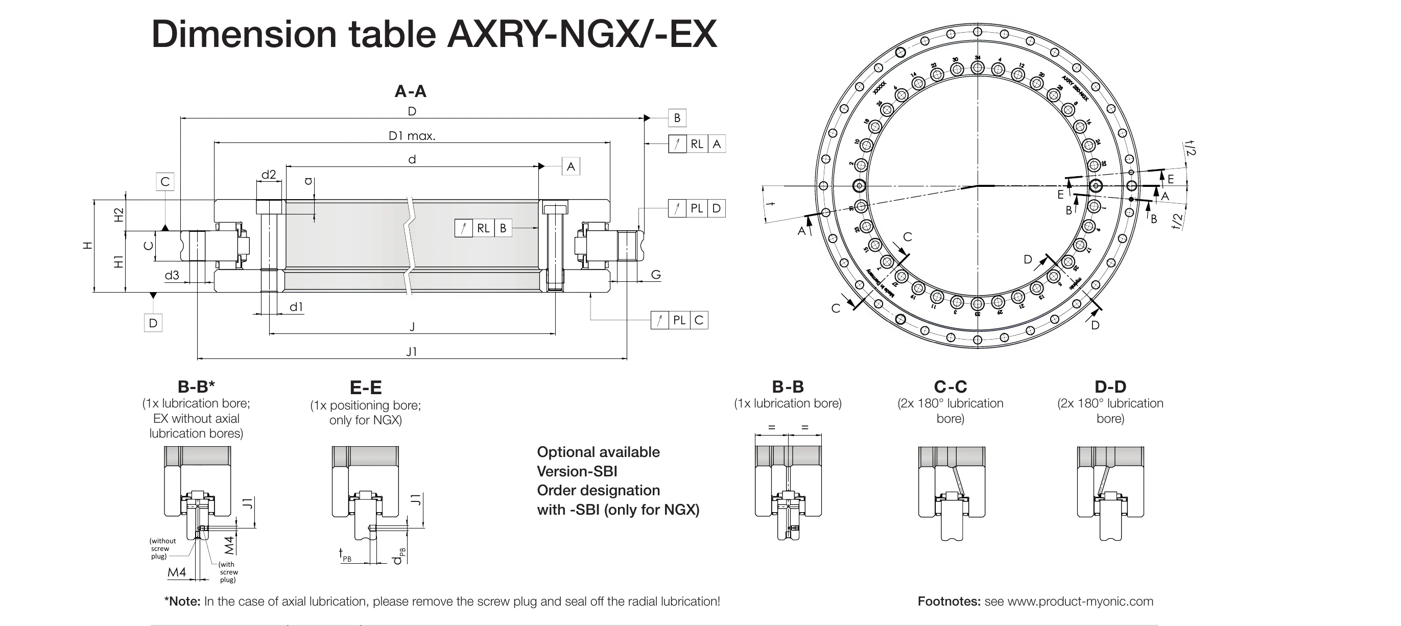
Main Dimensions
Dimensions in mm, weight in kg.
- m: Weight [kg]
- d: Bore diameter [mm] / ∆d: Bore diameter tolerance
- D: Outside diameter [mm] / ∆D: Outside diameter tolerance
- H: Overall height [mm]
- H1: Table-side height [mm] / ∆H1 (Standard): Standard accuracy tolerance / ∆H1 (Restricted): Restricted accuracy tolerance
- H2: Shaft-side height [mm] / ∆H2: H2 tolerance
- C: Chamfer (max.) [mm]
- D1: Bearing-bore-side diameter [mm] (max.)
- J: Pitch circle diameter of the inner ring fixing holes [mm] / J1: Pitch circle diameter of the outer ring fixing holes [mm]
| Model | m [kg] | d (bore) | D (outside) | H [mm] | H1 [mm] | ∆H1 | H2 [mm] | ∆H2 | C max [mm] | D1 max [mm] | J [mm] | J1 [mm] | |||
|---|---|---|---|---|---|---|---|---|---|---|---|---|---|---|---|
| mm | ∆d | mm | ∆D | Standard | Restricted | ||||||||||
| AXRY 50-EX | 1.6 | 50 | -0.008 | 126 | -0.011 | 30 | 20 | ±0.125 | ±0.025 | 10 | ±0.02 | 10 | 105 | 63 | 116 |
| AXRY 80-EX4) | 2.4 | 80 | -0.009 | 146 | -0.011 | 35 | 23.35 | ±0.150 | ±0.025 | 11.65 | ±0.02 | 12 | 130 | 92 | 138 |
| AXRY 100-EX4) | 4.1 | 100 | -0.010 | 185 | -0.015 | 38 | 25 | ±0.175 | ±0.025 | 13 | ±0.02 | 12 | 161 | 112 | 170 |
| AXRY 120-EX | 5.3 | 120 | -0.010 | 210 | -0.015 | 40 | 26 | ±0.175 | ±0.025 | 14 | ±0.02 | 12 | - | 135 | 195 |
| AXRY 150-EX | 6.2 | 150 | -0.013 | 240 | -0.015 | 40 | 26 | ±0.175 | ±0.03 | 14 | ±0.02 | 12 | 214 | 165 | 225 |
Fixing Holes
- d1: Through-hole diameter of the inner ring fixing holes [mm]
- d2: Counterbore diameter of the inner ring fixing holes [mm] (- means no counterbore)
- a: Counterbore depth of the inner ring fixing holes [mm] (- means no counterbore)
- Inner ring quantity: Number of inner ring fixing holes3)
- d3: Through-hole diameter of the outer ring fixing holes [mm]
- Outer ring quantity: Number of outer ring fixing holes3)
- G: Extraction thread size / Extraction thread quantity: Number of extraction thread holes
- nxt: Number of fixing holes × pitch angle (including fastening screws or extraction threads)1)
- MA: Screw tightening torque2) [Nm]
| Model | Inner ring fixing holes | Outer ring fixing holes | Extraction thread | nxt1) | MA2) [Nm] | |||||
|---|---|---|---|---|---|---|---|---|---|---|
| d1 [mm] | d2 [mm] | a [mm] | Quantity3) | d3 [mm] | Quantity3) | G | Quantity | |||
| AXRY 50-EX | 5.6 | - | - | 12 | 5.6 | 12 | M5 | 2 | 12 × 30° | 8.5 |
| AXRY 80-EX4) | 5.6 | 10 | 4.4 | 12 | 4.6 | 12 | M5 | 2 | 12 × 30° | 8.5 / 4.5 |
| AXRY 100-EX4) | 5.6 | 10 | 5.4 | 16 | 5.6 | 15 | M6 | 3 | 18 × 20° | 8.5 |
| AXRY 120-EX | 7 | 11 | 6.4 | 22 | 7 | 21 | M8 | 3 | 24 × 15° | 14 |
| AXRY 150-EX | 7 | 11 | 6.4 | 34 | 7 | 33 | M8 | 3 | 36 × 10° | 14 |
Load Ratings & Rigidity
Load in kN, speed in rpm, friction torque in Nm, runout in µm, rigidity in kN/µm or kNm/mrad, minimum corner radius in mm.
- Ca: Dynamic axial load rating [kN] / C0a: Static axial load rating [kN]
- Cr: Dynamic radial load rating [kN] / C0r: Static radial load rating [kN]
- nG: Limiting speed (grease)5) [rpm]
- MRL: Bearing friction torque (grease)6) [Nm]
- PL & RL Standard: Axial and radial runout — standard accuracy7) [µm]
- PL & RL Restricted: Axial and radial runout — restricted accuracy7) [µm]
- Cal: Axial rigidity [kN/µm] / Crl: Radial rigidity [kN/µm] / Ckl: Tilting rigidity [kNm/mrad]
- Rmin: Minimum corner radius [mm]
| Model | Load ratings [kN] | nG5) [rpm] | MRL6) [Nm] | Runout PL & RL7) [µm] | Cal [kN/µm] | Crl [kN/µm] | Ckl [kNm/mrad] | Rmin [mm] | ||||
|---|---|---|---|---|---|---|---|---|---|---|---|---|
| Ca | C0a | Cr | C0r | Standard | Restricted | |||||||
| AXRY 50-EX | 33.5 | 161.6 | 22.7 | 39.2 | 2000 | 1.5 | 2 | 1 | 2.4 | 1.2 | 2.5 | 0.6 |
| AXRY 80-EX4) | 39.5 | 215.4 | 51 | 104.9 | 1500 | 2.0 | 3 | 1.5 | 3 | 1.9 | 4.9 | 0.6 |
| AXRY 100-EX4) | 89.2 | 560.6 | 56.3 | 126.9 | 1300 | 2.0 | 3 | 1.5 | 4.1 | 2.4 | 10 | 0.8 |
| AXRY 120-EX | 95.3 | 640.6 | 62.1 | 152.9 | 1150 | 4.5 | 3 | 1.5 | 4.8 | 3 | 16.3 | 0.8 |
| AXRY 150-EX | 100.4 | 720.7 | 68.4 | 185 | 1000 | 7.0 | 3 | 1.5 | 5.4 | 3.7 | 25.1 | 0.8 |
1) Including fastening screws or extraction threads.
2) Tightening torque for screws acc. DIN 912, strength class 10.9.
3) Attention! For fixing holes in the adjacent construction, observe the pitch of the bearing bores.
4) The screw counterbores of the large L-ring open toward the bearing bore; the bearing inside diameter is not supported in this area.
5) Please enquire at sales@eb-system.com in case of high speed applications.
6) Friction torques as a reference value: measuring speed nconst = 5 min-1; with myonic standard grease and standard amount of grease; without support ring; the bearing friction torque can increase up to 2.5 times at the limiting speed.
7) Measured on an installed bearing with ideal adjacent construction.