Series Overview
The L7 Width 300 sub-series consists of three primary part lengths — 350-300, 500-300, and 650-300 — with a 300 mm secondary part width. Peak force range 12,157 ~ 24,313 N, water-cooled continuous force 5,667 ~ 11,229 N. 650-300 is the largest model in the L7 series, providing the series peak-force ceiling of 24,313 N, suitable for the most demanding machine tool spindles and heavy-duty machining.
Dimensions
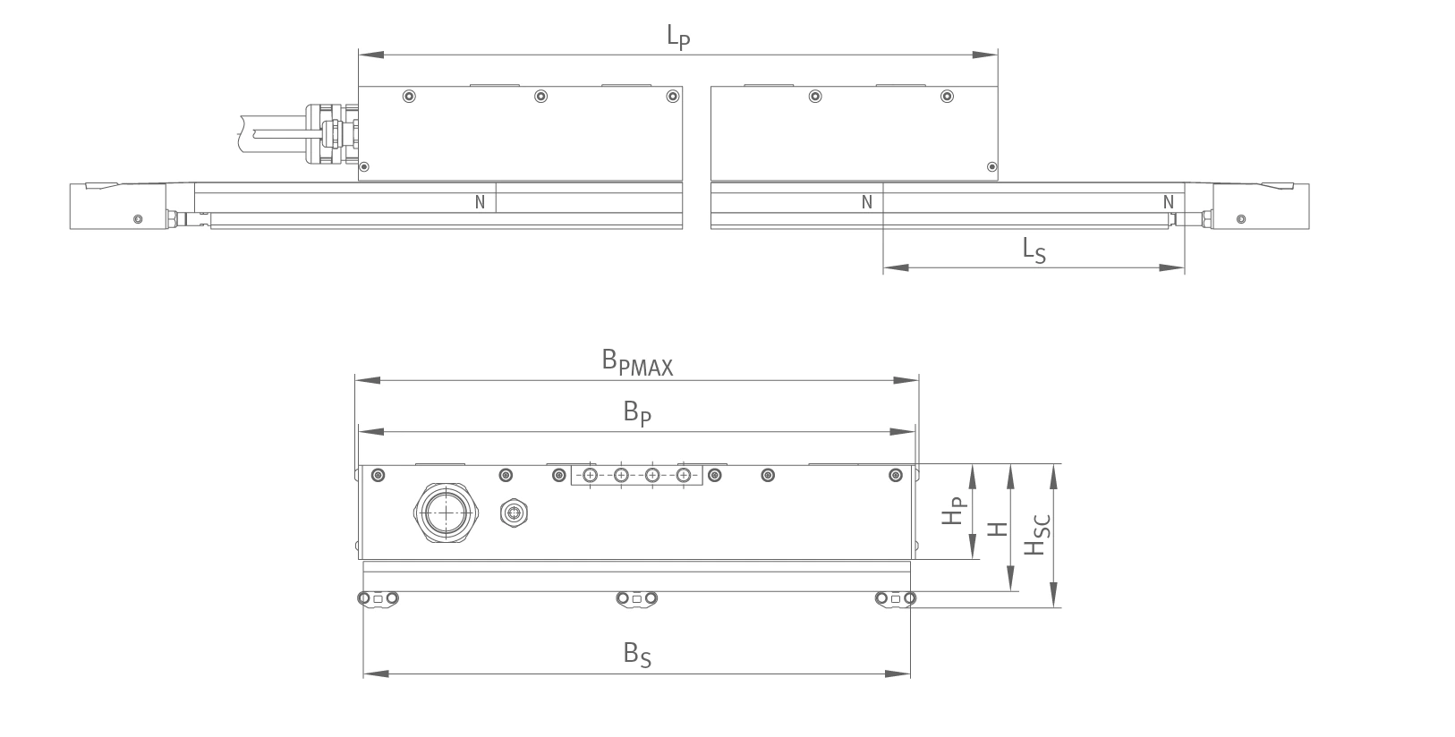
Side / end view dimensions (shared across the entire series)
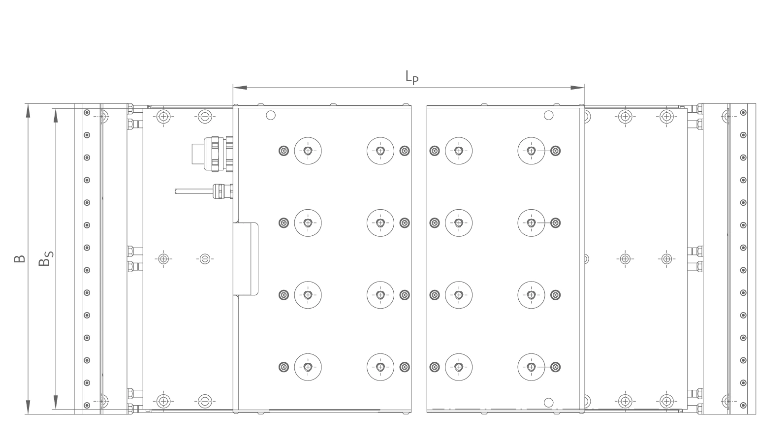
Top view dimensions (shared across the entire series)
Performance Data — Width 300
| Category / Parameter | Symbol | Unit | 350-300 | 500-300 | 650-300 |
|---|---|---|---|---|---|
| Winding | |||||
| Winding | — | — | Z2.8H | Z2.8H | Z3.8H |
| Forces | |||||
| Ultimate force (1 s) | Fu | N | 13,296 | 19,944 | 26,593 |
| Peak force | Fp | N | 12,157 | 18,235 | 24,313 |
| Continuous force (cooled) | Fcw | N | 5,667 | 8,415 | 11,229 |
| Continuous force (not cooled) | Fc | N | 1,838 | 2,629 | 3,437 |
| Stall force (cooled) | Fsw | N | 3,759 | 5,580 | 7,444 |
| Cogging force at I = 0 | Fcog | N | 24.31 | 36.47 | 48.63 |
| Velocities | |||||
| Limiting velocity at Ip, UDCL = 600 V | vlp600 | m/s | 0.88 | 0.56 | 0.76 |
| Limiting velocity at Icw, UDCL = 600 V | vlw600 | m/s | 2.04 | 1.42 | 1.82 |
| Limiting velocity at Ip, UDCL = 300 V | vlp300 | m/s | 0.27 | 0.03 | 0.20 |
| Limiting velocity at Icw, UDCL = 300 V | vlw300 | m/s | 0.88 | 0.58 | 0.78 |
| Currents | |||||
| Effective ultimate current (1 s) | Iu eff | A | 90.8 | 98.4 | 163.2 |
| Effective peak current | Ip eff | A | 72.7 | 78.7 | 130.5 |
| Effective continuous current (cooled) | Icw eff | A | 24.9 | 26.7 | 44.3 |
| Effective continuous current (not cooled) | Ic eff | A | 7.91 | 8.17 | 13.29 |
| Effective stall current (cooled) | Isw eff | A | 16.4 | 17.6 | 29.2 |
| Power losses | |||||
| Power loss at Fp | Plp | W | 17,414 | 26,275 | 34,725 |
| Power loss at Fcw | Plw | W | 2,738 | 4,047 | 5,357 |
| Power loss at Fc | Plc | W | 277 | 379 | 482 |
| Electrical characteristic values | |||||
| DC link voltage | UDCL | V | 800 | 800 | 800 |
| Electrical resistance, phase to phase | R20 | Ω | 2.20 | 2.82 | 1.36 |
| Inductance, phase to phase | L | mH | 42.88 | 54.78 | 26.57 |
| Back EMF constant | kû | V/(m/s) | 190.0 | 263.1 | 211.6 |
| General characteristic values | |||||
| Pole pair width | 2τp | mm | 46 | 46 | 46 |
| Motor constant (20 °C) | km | N/√W | 128.2 | 156.5 | 181.5 |
| Force constant | kf | N/A | 232.3 | 321.6 | 258.7 |
| Motor temperature switch-off | JPTC | °C | 110.0 | 110.0 | 110.0 |
| Attraction force | Fa | N | 18,615 | 27,922 | 37,230 |
| Cooling conditions (medium: water, supply temperature 20 °C) | |||||
| Recommended volume flow rate | dV/dt | l/min | 11.0 | 12.0 | 13.0 |
| Cooling water temperature difference | ΔJ | K | 3.6 | 4.8 | 5.9 |
| Pressure drop | Δp | bar | 0.8 | 1.3 | 1.9 |
Geometric Data — Width 300
| Category / Dimension | Symbol | Unit | 350-300 | 500-300 | 650-300 |
|---|---|---|---|---|---|
| Primary part | |||||
| Length | LP | mm | 384 | 545 | 706 |
| Width | BP | mm | 340 | 340 | 340 |
| Height | HP | mm | 58.5 | 58.5 | 58.5 |
| Maximum width | BPMAX | mm | 344.4 | 344.4 | 344.4 |
| Cooling water connection | TSPC | — | 4 × G1/8″ | 4 × G1/8″ | 4 × G1/8″ |
| Mass | mP | kg | ca. 39 | ca. 55 | ca. 72 |
| Secondary part | |||||
| Length | LS | mm | 184 | ||
| Width | BS | mm | 334 | ||
| Height (without encapsulation) | HS | mm | 18 | ||
| Height (encapsulated) | HSP | mm | 18.3 | ||
| Motor installation dimensions | |||||
| Width with secondary part cooling system | B | mm | 345 | ||
| Height without secondary part cooling system | H | mm | 78 | ||
| Height with secondary part cooling system | HSC | mm | 88 | ||
Specifications subject to change without notice.
Source: Schaeffler Industrial Drives — L7 Series High Efficiency Linear Motors (PHL en-GB / DE / 2025-01).
For parameter definitions see the Type Designation & Glossary page.