LDDS-078 · LDDS-081 Technical Data
System Data
| Parameter | Symbol | Unit | LDDS-078 with M10x1 thread adapter | LDDS-081 with M10x1 thread adapter |
|---|---|---|---|---|
| Width | W | mm | 28.6 (without cover screw heads) 31.1 (with cover screw heads) | |
| Length | L | mm | 46.6 (without cable outlet) 53.7 (with cable outlet) | |
| Height | H | mm | 102.8 | 110.8 |
| Total mass (without cable) | m | g | 776 | 825 |
| Moving mass | mmov | g | 77 | 88 |
| Maximum stroke (from hard stop to hard stop) | s | mm | 5 | 10 |
| Maximum speed | vmax | m/s | 2 | 2 |
| Maximum acceleration | amax | m/s² | 300 | 300 |
| Material | Steel | Steel | ||
| Cable length | Lcable | m | 1 | 1 |
System Components — Standard Encoder
| Parameter | Symbol | Unit | LDDS-078 with M10x1 thread adapter | LDDS-081 with M10x1 thread adapter |
|---|---|---|---|---|
| Guidance | Precision roller bearing | |||
| Friction | FFr | N | < 0.6 | |
| Weight compensation (force) | FWc | N | 1.5 | 0.4 (if available) |
| Encoder type (standard) | Linear magnetic incremental | |||
| Resolution | µm | 0.9765625 (1 mm/1024) | ||
| Reference mark | Periodic at a distance of 4 mm, first one at approx. 0.3 mm from upper hard stop | |||
| Accuracy | µm | ±15 | ±20 | |
| Repeat accuracy | µm | ±2 | ±2 | |
| Interface | RS 422 Output: quadrature signals A, B, Z and inverted signals | |||
| Minimal edge spacing | ns | 500 | 500 | |
| Power supply | V | 5 (100 mA) | 5 (100 mA) | |
System Components — Optional Encoder
| Parameter | Symbol | Unit | LDDS-078 with M10x1 thread adapter | LDDS-081 with M10x1 thread adapter |
|---|---|---|---|---|
| Encoder type (optional) | Linear optical incremental | |||
| Resolution | µm | 0.1 | 0.1 | |
| Reference mark | 1 (approx. 0.3 mm from upper hard stop) | |||
| Accuracy | µm | ±3 | ±3 | |
| Repeat accuracy | µm | ±1 | ±1 | |
| Interface | RS 422 Output: quadrature signals A, B, Z and inverted signals, or sinusoidal signal 1 Vpp (sin/cos), or absolute SSI or BiSS | |||
| Minimal edge spacing | ns | 37.5 | 37.5 | |
| Power supply | V | 5 (100 mA) | 5 (100 mA) | |
Motor Data
| Parameter | Symbol | Unit | LDDS-078 with M10x1 thread adapter | LDDS-081 with M10x1 thread adapter |
|---|---|---|---|---|
| Motor type | 1-phase moving coil | |||
| Ultimate force (1 s) at Iu | Fu | N | 65 | 64 |
| Peak force (3 s) at Ip | Fp | N | 48 | 48 |
| Continuous force at Ic | Fc | N | 24 | 23 |
| Ultimate current (1 s) | Iu | A | 8.0 | 8.0 |
| Peak current (3 s) | Ip | A | 6.0 | 6.0 |
| Continuous current | Ic | A | 3.0 | 3.0 |
| Power loss at Fp | Plp | W | 22.0 | 28.0 |
| Power loss at Fc | Plc | W | 5.5 | 6.5 |
| Motor constant (25°C) | km | Nm/√W | 10.3 | 9.1 |
| Maximum force constant | kf | N/A | 8.1 | 8.0 |
| Back EMF constant | ku | V/(m/s) | 8.1 | 8.0 |
| Electrical resistance (25°C) | R25 | Ω | 0.62 | 0.77 |
| Electrical inductance | L | mH | 0.5 | 0.5 |
| Thermal time constant at housing | τth | min | 30 | 30 |
| Maximum DC link voltage | UDCL | V | 48 | 48 |
Force-Stroke Characteristics
Moving Direction of the Linear Direct Drive System
When the motor is powered according to the circuit diagram, the push pin is moving out of the housing.
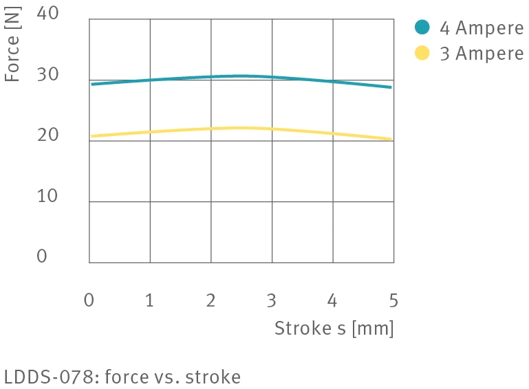
LDDS-078: force vs. stroke
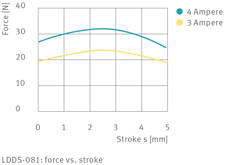
LDDS-081: force vs. stroke
Interface to the Application
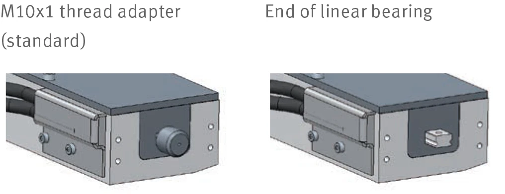
Left: M10x1 thread adapter (standard) Right: End of linear bearing
Motor Terminal Assignment
Cable, 2 × 0.34 mm²
| Wire | Signal |
|---|---|
| WH (white) | Phase 1- |
| BN (brown) | Phase 1+ |
| BK (black) | Shield |
Encoder RS 422 Terminal Assignment
D-connector, 9-pin, male · Cable, 8 × 0.08 mm²
| Pin | Wire | Signal |
|---|---|---|
| 1 | RD (red) | +5 V |
| 2 | WH (white) | A+ |
| 3 | BN (brown) | A- |
| 4 | GN (green) | B+ |
| 5 | YE (yellow) | B- |
| 6 | GY (grey) | Z+ |
| 7 | PK (pink) | Z- |
| 8 | BU (blue) | GND |
| Case | Shield |
Drawing
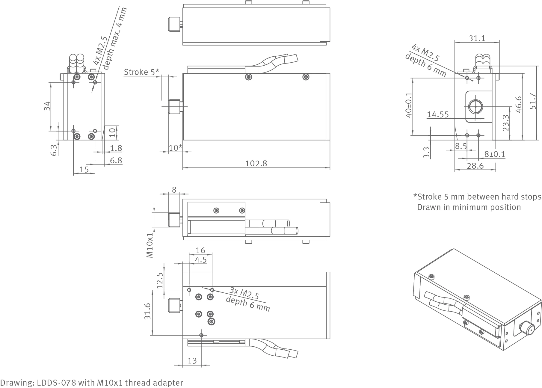
LDDS-078 with M10x1 thread adapter
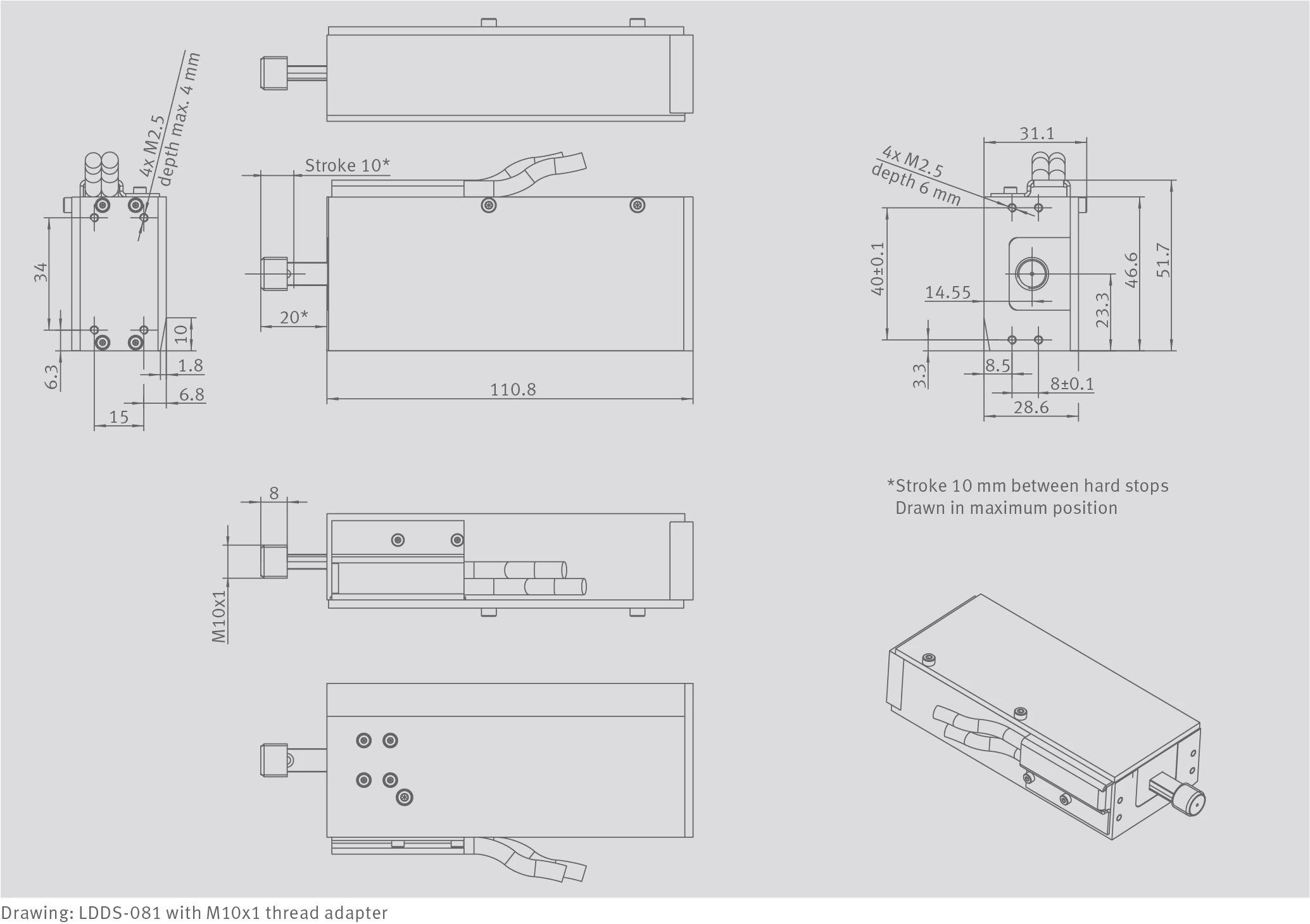
LDDS-081 with M10x1 thread adapter