Series Overview
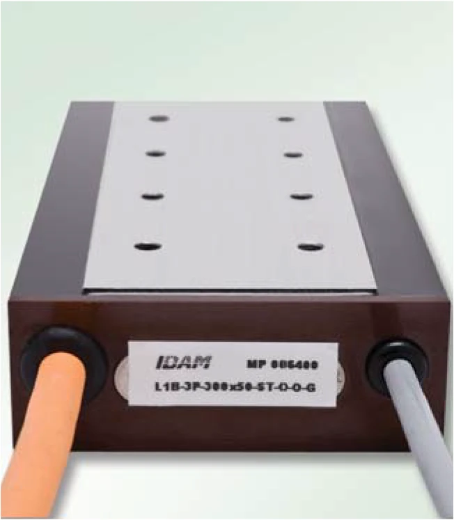
L1B is a high-force flat iron-core linear motor with an installation height of 39 mm. Compared to L1A, L1B delivers higher continuous force at the same power dissipation, making it ideal for applications where thermal efficiency is a priority.
The L1B series is available in three coil lengths (100 / 200 / 300 mm) and three widths (25 / 50 / 75 mm), giving 9 model combinations.
Dimensional Drawing
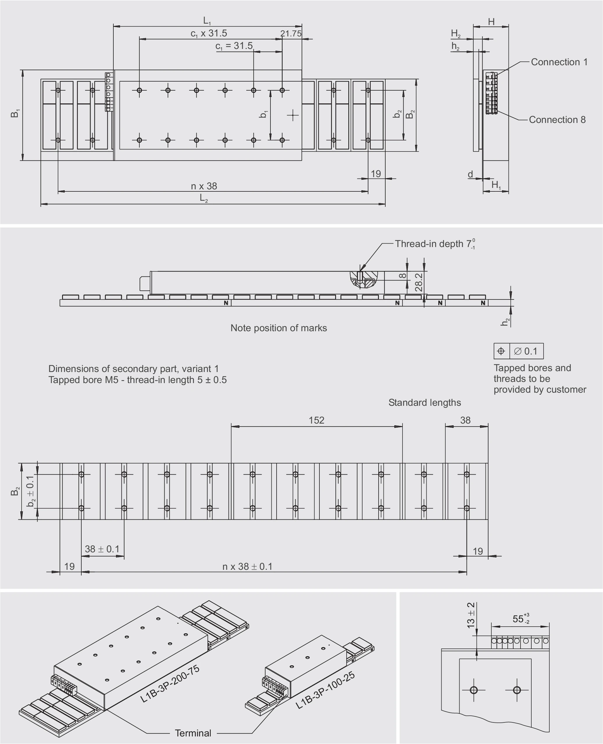
L1B-3P-100-B
Technical Data I — Mechanical Parameters
| Parameter | Symbol | Unit | 100-25-WM | 100-50-WM | 100-75-WM |
|---|---|---|---|---|---|
| Primary Part (Coil Assembly) | |||||
| Length | L1 | mm | 113 | 113 | 113 |
| Width | B1 | mm | 57 | 82 | 107 |
| Height | H1 | mm | 28.2 | 28.2 | 28.2 |
| Mass | m1 | kg | 0.7 | 1.2 | 1.7 |
| M5 threaded holes (L × W) | — | — | 3 × 1 | 3 × 2 | 3 × 2 |
| M5 hole pitch / length direction | nl × c1 | mm | 2 × 31.5 | 2 × 31.5 | 2 × 31.5 |
| M5 hole pitch / width direction | nb × b1 | mm | — | 1 × 30 | 1 × 55 |
| Motor cable diameter | dK | mm | 7.3 | 7.3 | 7.3 |
| Secondary Part — Through-hole type (variant 2) | |||||
| Width | B2 | mm | 50 | 80 | 100 |
| Mass (length 38 / 152 mm) | m2 | kg/pc | 0.11/0.44 | 0.19/0.76 | 0.24/0.96 |
| Magnetic base height | h2 | mm | 6 | 6 | 6 |
| Height | H2 | mm | 10 | 10 | 10 |
| M5 DIN 6912 through-hole spacing | b3 | mm | 37 | 62 | 87 |
| Secondary Part — Threaded hole type (variant 1) | |||||
| Width | B2 | mm | 30 | 50 | 80 |
| Mass (length 38 / 152 mm) | m2 | kg/pc | 0.076/0.30 | 0.13/0.52 | 0.21/0.84 |
| Magnetic base height | h2 | mm | 6 | 6 | 6 |
| Height | H2 | mm | 10 | 10 | 10 |
| M5 threaded holes (from bottom) | b2 | mm | 15 | 30 | 55 |
| Installation Dimensions | |||||
| Total height (PRIM + SEC) | H | mm | 39 -0.1 | 39 -0.1 | 39 -0.1 |
| Mechanical air gap | d | mm | ≈ 0.8 | ≈ 0.8 | ≈ 0.8 |
| Maximum width | B | mm | 57 | 82 | 107 |
| Secondary part length (38 mm grid) | L2 | mm | L1 + stroke | L1 + stroke | L1 + stroke |
| Cable length | LK | mm | ≈ 1000 | ≈ 1000 | ≈ 1000 |
Technical Data II — Electrical Performance
| Parameter | Symbol | Unit | 100-25-WM | 100-50-WM | 100-75-WM |
|---|---|---|---|---|---|
| Limit force (Iu) | Fu | N | 200 | 398 | 594 |
| Peak force — saturated (Ip) | Fp | N | 171 | 340 | 507 |
| Peak force — linear (Ipl) | Fpl | N | 113 | 225 | 335 |
| Continuous force (Ic) | Fc | N | 52 | 106 | 159 |
| Power loss at Fp (25 °C) | Plp | W | 317 | 464 | 610 |
| Power loss at Fpl (25 °C) | Plpl | W | 89 | 130 | 171 |
| Power loss at Fc (25 °C) | Plc | W | 19 | 29 | 38 |
| Motor constant (25 °C) | km | N/√W | 12.0 | 19.7 | 25.6 |
| Damping constant (short circuit) | kd | N/(m/s) | 144 | 389 | 658 |
| Electrical time constant | τel | ms | 5.19 | 7.09 | 8.08 |
| Attraction force | Fa | N | 584 | 1168 | 1752 |
| Cogging force (typical) | Fr | N | 6 | 12 | 18 |
| Pole pair width | 2τp | mm | 38 | 38 | 38 |

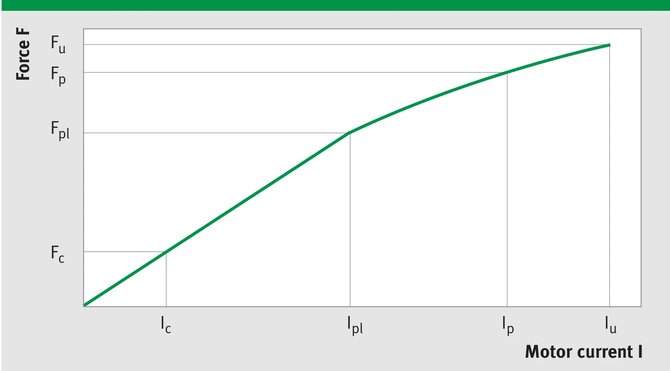
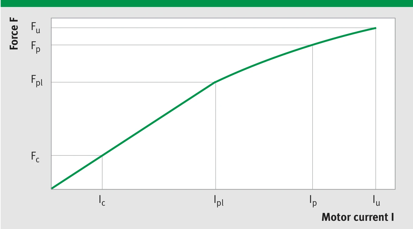
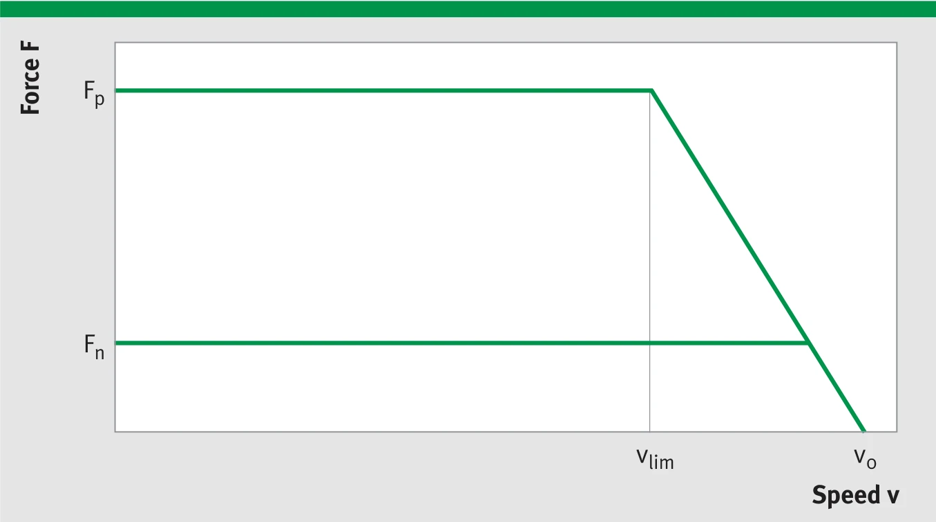
L1B-3P-100-B Force-Speed (F-v) and Force-Current (F-I) characteristic curves
The achievable speed limit depends on operating voltage (UDCL) and current (force). The diagram shows the idealised envelope with the key operating points at peak current (Fp, vlim) and at idle (Fo, v0).
Technical Data III — Winding Data
| Parameter | Symbol | Unit | 100-25-WM | 100-50-WM | 100-75-WM |
|---|---|---|---|---|---|
| Force constant | kf | N/Arms | 29.4 | 58.5 | 62.4 |
| Back EMF constant (phase-to-phase) | ku | V/(m/s) | 24.1 | 47.9 | 51.1 |
| Limit speed (Ip, UDCL=300 VDC) | vlim | m/s | 6.8 | 3.1 | 3.0 |
| Limit speed (Ip, UDCL=600 VDC) | vlim | m/s | 14.6 | 7.1 | 6.7 |
| Resistance (phase-to-phase, 25 °C) | R25 | Ω | 4.02 | 5.88 | 3.95 |
| Inductance (phase-to-phase) | L | mH | 20.83 | 41.66 | 31.92 |
| Limit current | Iu | Arms | 9.1 | 9.1 | 12.7 |
| Peak current (saturated) | Ip | Arms | 7.3 | 7.3 | 10.2 |
| Peak current (linear) | Ipl | Arms | 3.8 | 3.8 | 5.4 |
| Continuous current | Ic | Arms | 1.8 | 1.8 | 2.5 |
| Permissible temperature (at sensor) | θ | °C | 100 | 100 | 100 |
| Maximum DC bus voltage | UDCL | V | 600 | 600 | 600 |
L1B-3P-100-B winding parameter characteristic
Note: The winding variant WM (standard) described above is suitable for moderately dynamic performance requirements. The winding variants WL and WH suitable for lower and higher dynamic performance requirements are available upon request. The integrated temperature sensors do not display the exact winding temperature. Depending on current load, the winding temperature may be up to approx. 30 K higher.
L1B-3P-200-B
Technical Data I — Mechanical Parameters
| Parameter | Symbol | Unit | 200-25-WM | 200-50-WM | 200-75-WM |
|---|---|---|---|---|---|
| Primary Part (Coil Assembly) | |||||
| Length | L1 | mm | 208 | 208 | 208 |
| Width | B1 | mm | 57 | 82 | 107 |
| Height | H1 | mm | 28.2 | 28.2 | 28.2 |
| Mass | m1 | kg | 1.4 | 2.3 | 3.2 |
| M5 threaded holes (L × W) | — | — | 6 × 1 | 6 × 2 | 6 × 2 |
| M5 hole pitch / length direction | nl × c1 | mm | 5 × 31.5 | 5 × 31.5 | 5 × 31.5 |
| M5 hole pitch / width direction | nb × b1 | mm | — | 1 × 30 | 1 × 55 |
| Motor cable diameter | dK | mm | 7.3 | 7.3 | 7.3 |
| Secondary Part — Through-hole type (variant 2) | |||||
| Width | B2 | mm | 50 | 80 | 100 |
| Mass (length 38 / 152 mm) | m2 | kg/pc | 0.11/0.44 | 0.19/0.76 | 0.24/0.96 |
| Magnetic base height | h2 | mm | 6 | 6 | 6 |
| Height | H2 | mm | 10 | 10 | 10 |
| M5 DIN 6912 through-hole spacing | b3 | mm | 37 | 62 | 87 |
| Secondary Part — Threaded hole type (variant 1) | |||||
| Width | B2 | mm | 30 | 50 | 80 |
| Mass (length 38 / 152 mm) | m2 | kg/pc | 0.076/0.30 | 0.13/0.52 | 0.21/0.84 |
| Magnetic base height | h2 | mm | 6 | 6 | 6 |
| Height | H2 | mm | 10 | 10 | 10 |
| M5 threaded holes (from bottom) | b2 | mm | 15 | 30 | 55 |
| Installation Dimensions | |||||
| Total height (PRIM + SEC) | H | mm | 39 -0.1 | 39 -0.1 | 39 -0.1 |
| Mechanical air gap | d | mm | ≈ 0.8 | ≈ 0.8 | ≈ 0.8 |
| Maximum width | B | mm | 57 | 82 | 107 |
| Secondary part length (38 mm grid) | L2 | mm | L1 + stroke | L1 + stroke | L1 + stroke |
| Cable length | LK | mm | ≈ 1000 | ≈ 1000 | ≈ 1000 |
Technical Data II — Electrical Performance
| Parameter | Symbol | Unit | 200-25-WM | 200-50-WM | 200-75-WM |
|---|---|---|---|---|---|
| Limit force (Iu) | Fu | N | 400 | 796 | 1188 |
| Peak force — saturated (Ip) | Fp | N | 341 | 679 | 1014 |
| Peak force — linear (Ipl) | Fpl | N | 226 | 449 | 670 |
| Continuous force (Ic) | Fc | N | 100 | 200 | 299 |
| Power loss at Fp (25 °C) | Plp | W | 634 | 928 | 1220 |
| Power loss at Fpl (25 °C) | Plpl | W | 177 | 260 | 341 |
| Power loss at Fc (25 °C) | Plc | W | 34 | 51 | 68 |
| Motor constant (25 °C) | km | N/√W | 16.9 | 27.9 | 36.3 |
| Damping constant (short circuit) | kd | N/(m/s) | 287 | 777 | 1316 |
| Electrical time constant | τel | ms | 5.19 | 7.09 | 8.08 |
| Attraction force | Fa | N | 1128 | 2256 | 3383 |
| Cogging force (typical) | Fr | N | 7 | 14 | 21 |
| Pole pair width | 2τp | mm | 38 | 38 | 38 |
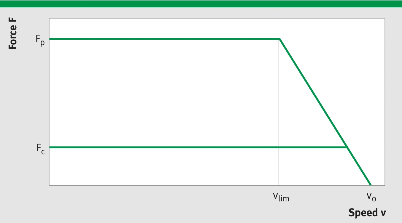
L1B-3P-200-B Force-Speed (F-v) and Force-Current (F-I) characteristic curves
The achievable speed limit depends on operating voltage (UDCL) and current (force). The diagram shows the idealised envelope with the key operating points at peak current (Fp, vlim) and at idle (Fo, v0).
Technical Data III — Winding Data
| Parameter | Symbol | Unit | 200-25-WM | 200-50-WM | 200-75-WM |
|---|---|---|---|---|---|
| Force constant | kf | N/Arms | 29.4 | 58.5 | 62.4 |
| Back EMF constant (phase-to-phase) | ku | V/(m/s) | 24.1 | 47.9 | 51.1 |
| Limit speed (Ip, UDCL=300 VDC) | vlim | m/s | 6.8 | 3.1 | 3.0 |
| Limit speed (Ip, UDCL=600 VDC) | vlim | m/s | 14.6 | 7.1 | 6.7 |
| Resistance (phase-to-phase, 25 °C) | R25 | Ω | 2.01 | 2.94 | 1.97 |
| Inductance (phase-to-phase) | L | mH | 10.41 | 20.83 | 15.96 |
| Limit current | Iu | Arms | 18.1 | 18.1 | 25.4 |
| Peak current (saturated) | Ip | Arms | 14.5 | 14.5 | 20.3 |
| Peak current (linear) | Ipl | Arms | 7.7 | 7.7 | 10.7 |
| Continuous current | Ic | Arms | 3.4 | 3.4 | 4.8 |
| Permissible temperature (at sensor) | θ | °C | 100 | 100 | 100 |
| Maximum DC bus voltage | UDCL | V | 600 | 600 | 600 |
L1B-3P-200-B winding parameter characteristic
Note: The winding variant WM (standard) described above is suitable for moderately dynamic performance requirements. The winding variants WL and WH suitable for lower and higher dynamic performance requirements are available upon request. The integrated temperature sensors do not display the exact winding temperature. Depending on current load, the winding temperature may be up to approx. 30 K higher.
L1B-3P-300-B
Technical Data I — Mechanical Parameters
| Parameter | Symbol | Unit | 300-25-WM | 300-50-WM | 300-75-WM |
|---|---|---|---|---|---|
| Primary Part (Coil Assembly) | |||||
| Length | L1 | mm | 303 | 303 | 303 |
| Width | B1 | mm | 57 | 82 | 107 |
| Height | H1 | mm | 28.2 | 28.2 | 28.2 |
| Mass | m1 | kg | 2.0 | 3.4 | 4.8 |
| M5 threaded holes (L × W) | — | — | 9 × 1 | 9 × 2 | 9 × 2 |
| M5 hole pitch / length direction | nl × c1 | mm | 8 × 31.5 | 8 × 31.5 | 8 × 31.5 |
| M5 hole pitch / width direction | nb × b1 | mm | — | 1 × 30 | 1 × 55 |
| Motor cable diameter | dK | mm | 7.3 | 7.3 | 7.3 |
| Secondary Part — Through-hole type (variant 2) | |||||
| Width | B2 | mm | 50 | 80 | 100 |
| Mass (length 38 / 152 mm) | m2 | kg/pc | 0.11/0.44 | 0.19/0.76 | 0.24/0.96 |
| Magnetic base height | h2 | mm | 6 | 6 | 6 |
| Height | H2 | mm | 10 | 10 | 10 |
| M5 DIN 6912 through-hole spacing | b3 | mm | 37 | 62 | 87 |
| Secondary Part — Threaded hole type (variant 1) | |||||
| Width | B2 | mm | 30 | 50 | 80 |
| Mass (length 38 / 152 mm) | m2 | kg/pc | 0.076/0.30 | 0.13/0.52 | 0.21/0.84 |
| Magnetic base height | h2 | mm | 6 | 6 | 6 |
| Height | H2 | mm | 10 | 10 | 10 |
| M5 threaded holes (from bottom) | b2 | mm | 15 | 30 | 55 |
| Installation Dimensions | |||||
| Total height (PRIM + SEC) | H | mm | 39 -0.1 | 39 -0.1 | 39 -0.1 |
| Mechanical air gap | d | mm | ≈ 0.8 | ≈ 0.8 | ≈ 0.8 |
| Maximum width | B | mm | 57 | 82 | 107 |
| Secondary part length (38 mm grid) | L2 | mm | L1 + stroke | L1 + stroke | L1 + stroke |
| Cable length | LK | mm | ≈ 1000 | ≈ 1000 | ≈ 1000 |
Technical Data II — Electrical Performance
| Parameter | Symbol | Unit | 300-25-WM | 300-50-WM | 300-75-WM |
|---|---|---|---|---|---|
| Limit force (Iu) | Fu | N | 600 | 1194 | 1782 |
| Peak force — saturated (Ip) | Fp | N | 512 | 1019 | 1521 |
| Peak force — linear (Ipl) | Fpl | N | 339 | 674 | 1005 |
| Continuous force (Ic) | Fc | N | 147 | 292 | 436 |
| Power loss at Fp (25 °C) | Plp | W | 951 | 1392 | 1832 |
| Power loss at Fpl (25 °C) | Plpl | W | 266 | 389 | 512 |
| Power loss at Fc (25 °C) | Plc | W | 50 | 73 | 96 |
| Motor constant (25 °C) | km | N/√W | 20.8 | 34.1 | 44.4 |
| Damping constant (short circuit) | kd | N/(m/s) | 431 | 1166 | 1972 |
| Electrical time constant | τel | ms | 5.19 | 7.09 | 8.08 |
| Attraction force | Fa | N | 1672 | 3343 | 5015 |
| Cogging force (typical) | Fr | N | 8 | 16 | 24 |
| Pole pair width | 2τp | mm | 38 | 38 | 38 |
L1B-3P-300-B Force-Speed (F-v) and Force-Current (F-I) characteristic curves
The achievable speed limit depends on operating voltage (UDCL) and current (force). The diagram shows the idealised envelope with the key operating points at peak current (Fp, vlim) and at idle (Fo, v0).
Technical Data III — Winding Data
| Parameter | Symbol | Unit | 300-25-WM | 300-50-WM | 300-75-WM |
|---|---|---|---|---|---|
| Force constant | kf | N/Arms | 29.4 | 58.5 | 87.3 |
| Back EMF constant (phase-to-phase) | ku | V/(m/s) | 24.1 | 47.9 | 71.4 |
| Limit speed (Ip, UDCL=300 VDC) | vlim | m/s | 6.8 | 3.1 | 1.9 |
| Limit speed (Ip, UDCL=600 VDC) | vlim | m/s | 14.6 | 7.1 | 4.5 |
| Resistance (phase-to-phase, 25 °C) | R25 | Ω | 1.34 | 1.96 | 2.58 |
| Inductance (phase-to-phase) | L | mH | 6.94 | 13.89 | 20.83 |
| Limit current | Iu | Arms | 27.2 | 27.2 | 27.2 |
| Peak current (saturated) | Ip | Arms | 21.8 | 21.8 | 21.8 |
| Peak current (linear) | Ipl | Arms | 11.5 | 11.5 | 11.5 |
| Continuous current | Ic | Arms | 5.0 | 5.0 | 5.0 |
| Permissible temperature (at sensor) | θ | °C | 100 | 100 | 100 |
| Maximum DC bus voltage | UDCL | V | 600 | 600 | 600 |

L1B-3P-300-B winding parameter characteristic
Note: The winding variant WM (standard) described above is suitable for moderately dynamic performance requirements. The winding variants WL and WH suitable for lower and higher dynamic performance requirements are available upon request. The integrated temperature sensors do not display the exact winding temperature. Depending on current load, the winding temperature may be up to approx. 30 K higher.
Notes
General tolerance: All values ±5% unless otherwise stated.
Special tolerance: Attraction force, cogging force, resistance and inductance values ±10%.
All electrical performance data are based on 25 °C ambient temperature.
The size specified for the air gap d is an auxiliary dimension and may fluctuate. The only technically relevant dimension is the specified overall installation height H, which must be complied with.
A stainless steel cover can be ordered separately for the secondary parts (not included in the standard equipment).