Primary Part Type Designation
UPLplus - 3P - H - L (- Sx )- PRIM
UPLplus = Series (U-shaped, printed, linear)
3P = 3-phase motor
H = Effective active height [mm]
L = Length of coil system [mm]
O / Sx = Version: O = Standard, Sx = Special version (customer-specific)
PRIM = Primary part
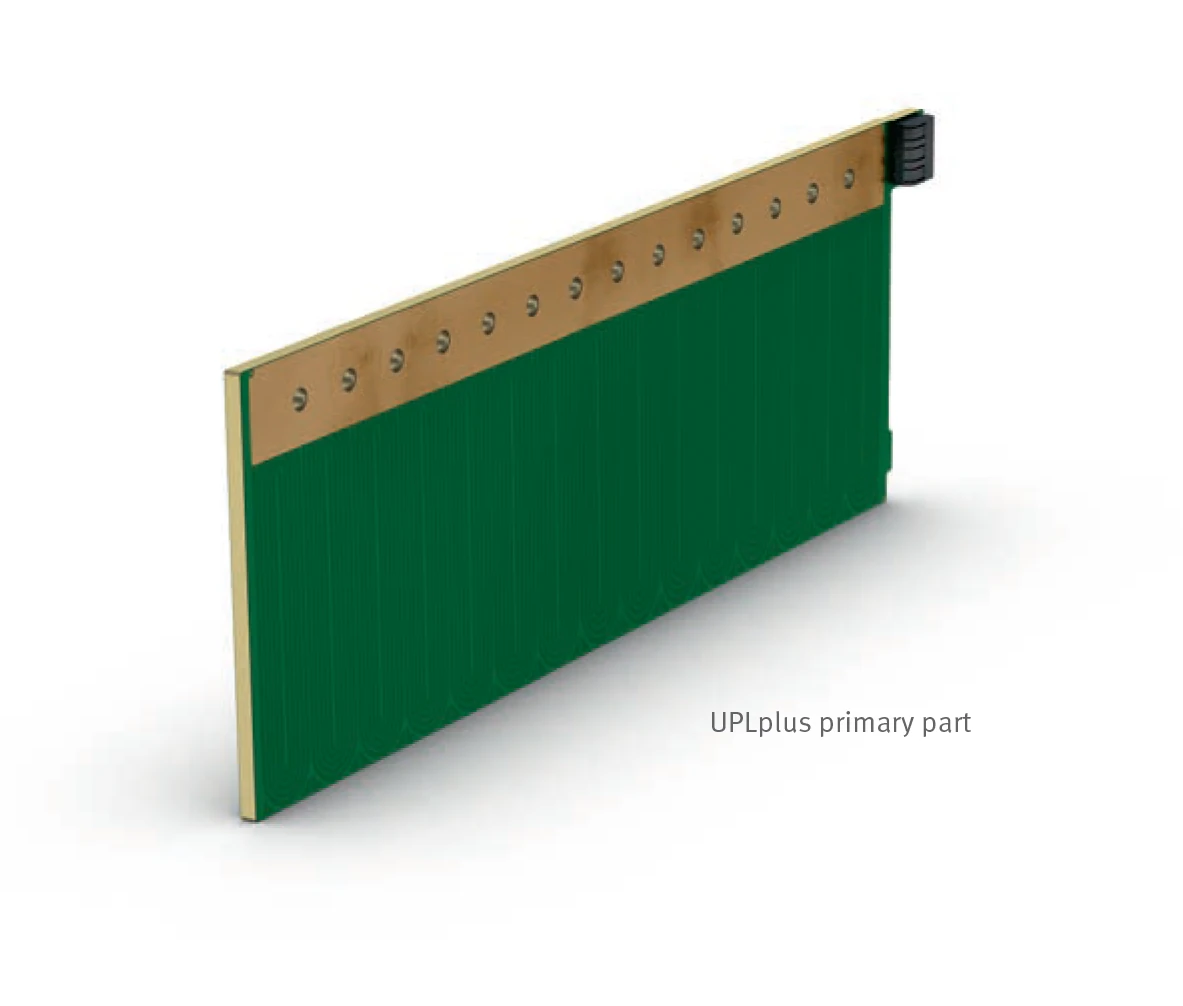
Primary Part Photo
Secondary Part Type Designation
UPLplus - H - L (- Sx )- SEK
UPLplus = Series
H = Effective active height [mm]
L = Length of secondary part [mm]
O / Sx = Version: O = Standard, Sx = Special version (customer-specific, optional)
SEK = Secondary part
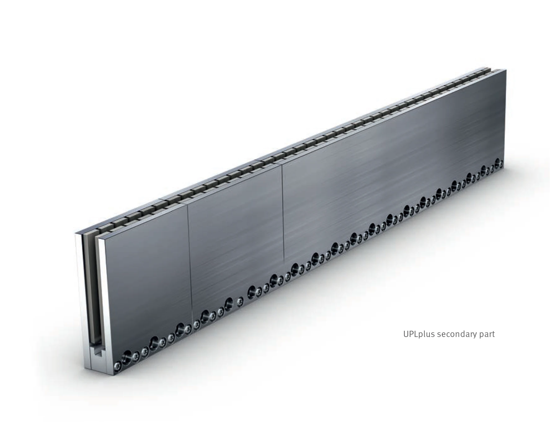
Secondary Part Photo
Glossary
The following symbols and terms are used in the UPLplus linear motor technical documentation.
| Symbol | Meaning | Unit | Description |
|---|---|---|---|
| Fmp | Impulse force | N | Motor force at max current density with impulse current Imp in millisecond range. Not for motor sizing. |
| Fp | Peak force | N | Motor force at peak current Ip. Duration heavily dependent on motor temperature, max 3s. Coil temp must not exceed 140°C. |
| Fcw | Nominal force, cooled (25°C at mounting base) | N | Constant force at Icw during rated operation with appropriate cooling; approx. 115K temp drop between winding and cooling. |
| Fc | Nominal force, not cooled | N | Force at Ic with equal phase loads; assumes mounting plate with ~3x surface area of primary part. |
| Imp | Impulse current | Arms | Maximum effective impulse current in millisecond range. |
| Ip | Peak current | Arms | Maximum effective peak current, max 3s. |
| Icw | Nominal current, cooled | Arms | Effective nominal current in continuous operation at 25°C mounting base. Winding resistance changes with actual temperature. |
| Ic | Nominal current, not cooled | Arms | Effective nominal current where power loss at defined mounting base size without compulsory cooling leads to max ~140°C motor temp. |
| Pl | Power loss | W | Thermal output in winding causing time-dependent temperature increase, dependent on operating mode and cooling conditions. Pl is calculated with the aid of the motor constant km: Pl = (F / km)². In the upper dynamic range (at Fp), the power loss is particularly high due to the square-law current dependency. |
| Plp | Power loss | W | Peak power loss at Ip. |
| Plcw | Power loss (25°C at mounting base) | W | Power loss at Icw. |
| Plc | Power loss | W | Power loss at Ic. |
| km | Motor constant | N/√W | Relation between generated force and power loss (efficiency). At 140°C winding temp, reduces to 0.85x normal value. |
| kf | Force constant | N/Arms | Winding parameter: F = Ic × kf in linear dynamic range. |
| ku | Back EMF constant | V/(m/s) | Armature countervoltage at motor terminals in generator operation: Ug = ku × v. |
| vp | Limit speed | m/s | Max speed at UDCL. Reached when force Fp at current Ip can be kept constant. Higher at lower currents/forces. |
| R25 | Electrical resistance | Ω | Winding resistance at 25°C. At 140°C, increases to 1.45x normal value. |
| Rth | Thermal resistance | K/W | Temperature difference between winding and cooling surface at specific power loss. |
| tth | Thermal time constant | s | Duration until 63% of max coil temperature (140°C) at nominal current. |
| L | Inductance | mH | Motor inductance, measured between two phases. |
| tel | Electrical time constant | ms | L/R ratio, approximately constant regardless of winding design. Controlled effective time constant decreases with voltage overshoot. |
| θ | Winding temperature | °C | Permissible winding temp recorded by sensors. Surface temp depends on installation, heat dissipation, and operating mode. |
| UDCL | DC link voltage | V | Supply voltage of power actuators. Must be higher at higher speeds due to countervoltage and frequency-dependent losses. |
| 2tp | Pole pair width | mm | Travel distance of a pole pair; tp is pole width (magnet width) in displacement direction with N/S alternating field. |