Series Introduction
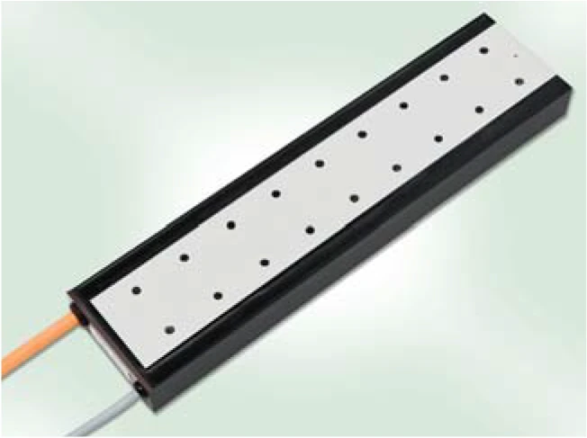
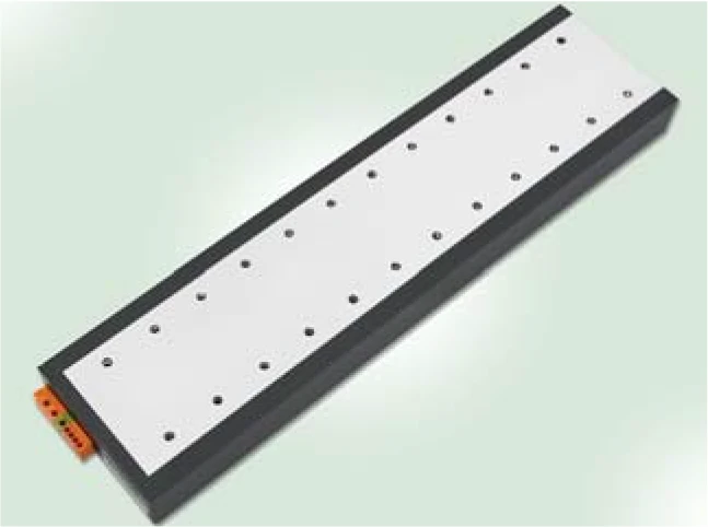
The L1A is a flat type linear motor with an installation height of only 31 mm, making it very compact with an excellent force-to-mass ratio. Available in two length specifications (100 mm and 200 mm) and three widths (25, 50, 75 mm), it is suitable for high-precision positioning applications with strict installation space constraints.
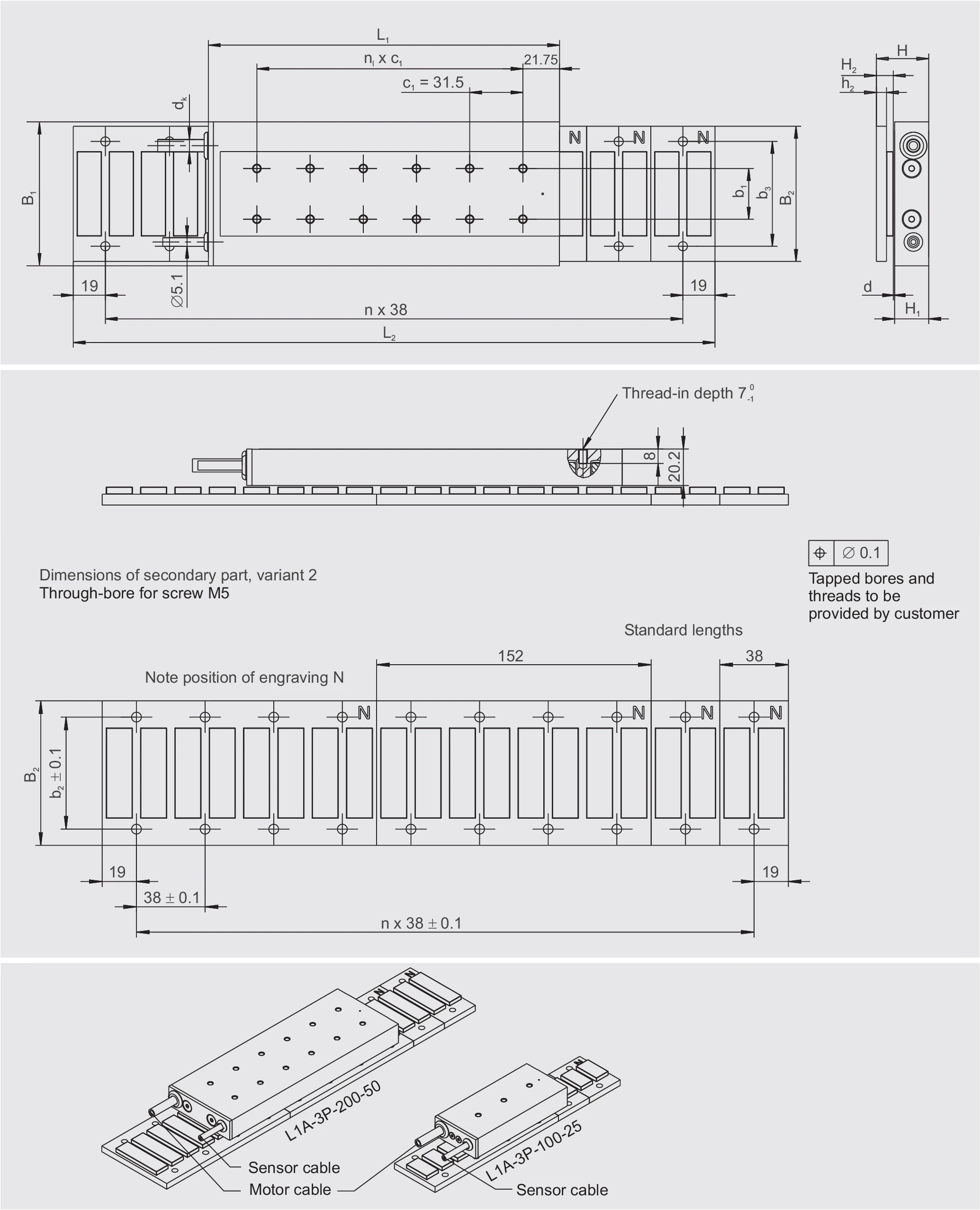
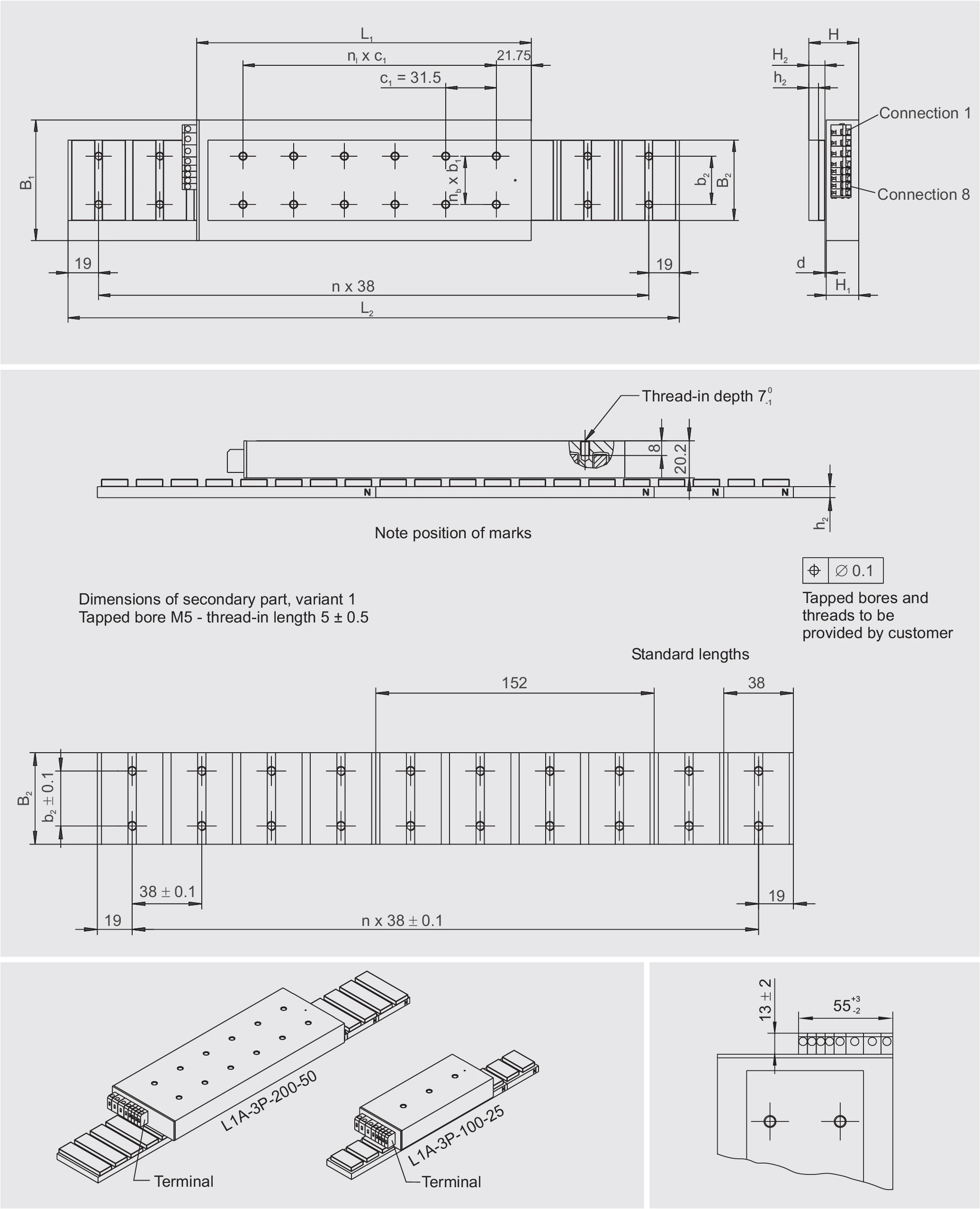
Dimensional Drawing
Cable Connection Version
Terminal Version
L1A-3P-100-B Technical Data
Technical Data I — Mechanical Parameters
| Parameter | Symbol | Unit | 100-25-WM | 100-50-WM | 100-75-WM |
|---|---|---|---|---|---|
| Primary Part | |||||
| Length | L1 | mm | 113 | 113 | 113 |
| Width | B1 | mm | 57 | 82 | 107 |
| Height | H1 | mm | 20.2 | 20.2 | 20.2 |
| Mass | m1 | kg | 0.5 | 0.8 | 1.2 |
| M5 threaded holes (L x W) | — | — | 3 x 1 | 3 x 2 | 3 x 2 |
| M5 thread pitch/length | nl x c1 | mm | 2 x 31.5 | 2 x 31.5 | 2 x 31.5 |
| M5 thread pitch/width | nb x b1 | mm | — | 1 x 30 | 1 x 55 |
| Motor cable diameter | dK | mm | 7.3 | 7.3 | 7.3 |
| Secondary Part — Through Hole (variant 2) | |||||
| Width | B2 | mm | 50 | 80 | 100 |
| Mass (length 38/152) | m2 | kg/unit | 0.11/0.44 | 0.19/0.76 | 0.24/0.96 |
| Magnetic base height | h2 | mm | 6 | 6 | 6 |
| Height | H2 | mm | 10 | 10 | 10 |
| Through hole (screw M5 DIN 6912) | b3 | mm | 37 | 62 | 87 |
| Secondary Part — Threaded Hole (variant 1) | |||||
| Width | B2 | mm | 30 | 50 | 80 |
| Mass (length 38/152) | m2 | kg/unit | 0.076/0.30 | 0.13/0.52 | 0.21/0.84 |
| Magnetic base height | h2 | mm | 6 | 6 | 6 |
| Height | H2 | mm | 10 | 10 | 10 |
| M5 threaded hole (from below) | b2 | mm | 15 | 30 | 55 |
| Installation Dimensions | |||||
| Total height PRIM + SEK | H | mm | 31 -0.1 | 31 -0.1 | 31 -0.1 |
| Mechanical air gap | d | mm | approx. 0.8 | approx. 0.8 | approx. 0.8 |
| Maximum width | B | mm | 57 | 82 | 107 |
| Secondary part length (38 mm grid) | L2 | mm | L1 + stroke | L1 + stroke | L1 + stroke |
| Cable length | LK | mm | ≈ 1000 | ≈ 1000 | ≈ 1000 |
Technical Data II — Electrical Performance Data
| Parameter | Symbol | Unit | 100-25-WM | 100-50-WM | 100-75-WM |
|---|---|---|---|---|---|
| Limit force (Iu) | Fu | N | 199 | 398 | 594 |
| Peak force (saturation) (Ip) | Fp | N | 169 | 338 | 505 |
| Peak force (linear) (Ipl) | Fpl | N | 117 | 235 | 351 |
| Continuous force (Ic) | Fc | N | 37 | 81 | 116 |
| Power loss (Ip, 25 °C) | Plp | W | 469 | 682 | 895 |
| Power loss (Ipl, 25 °C) | Plpl | W | 163 | 238 | 312 |
| Power loss (Ic, 25 °C) | Plc | W | 17 | 28 | 34 |
| Motor constant (25 °C) | km | N/√W | 9.2 | 15.2 | 19.9 |
| Damping constant (short circuit) | kd | N/(m/s) | 84 | 232 | 394 |
| Electrical time constant | τel | ms | 2.75 | 3.78 | 4.32 |
| Attraction force | Fa | N | 584 | 1168 | 1752 |
| Force ripple (typical cogging) | Fr | N | 6 | 12 | 18 |
| Pole pair width | 2τp | mm | 38 | 38 | 38 |
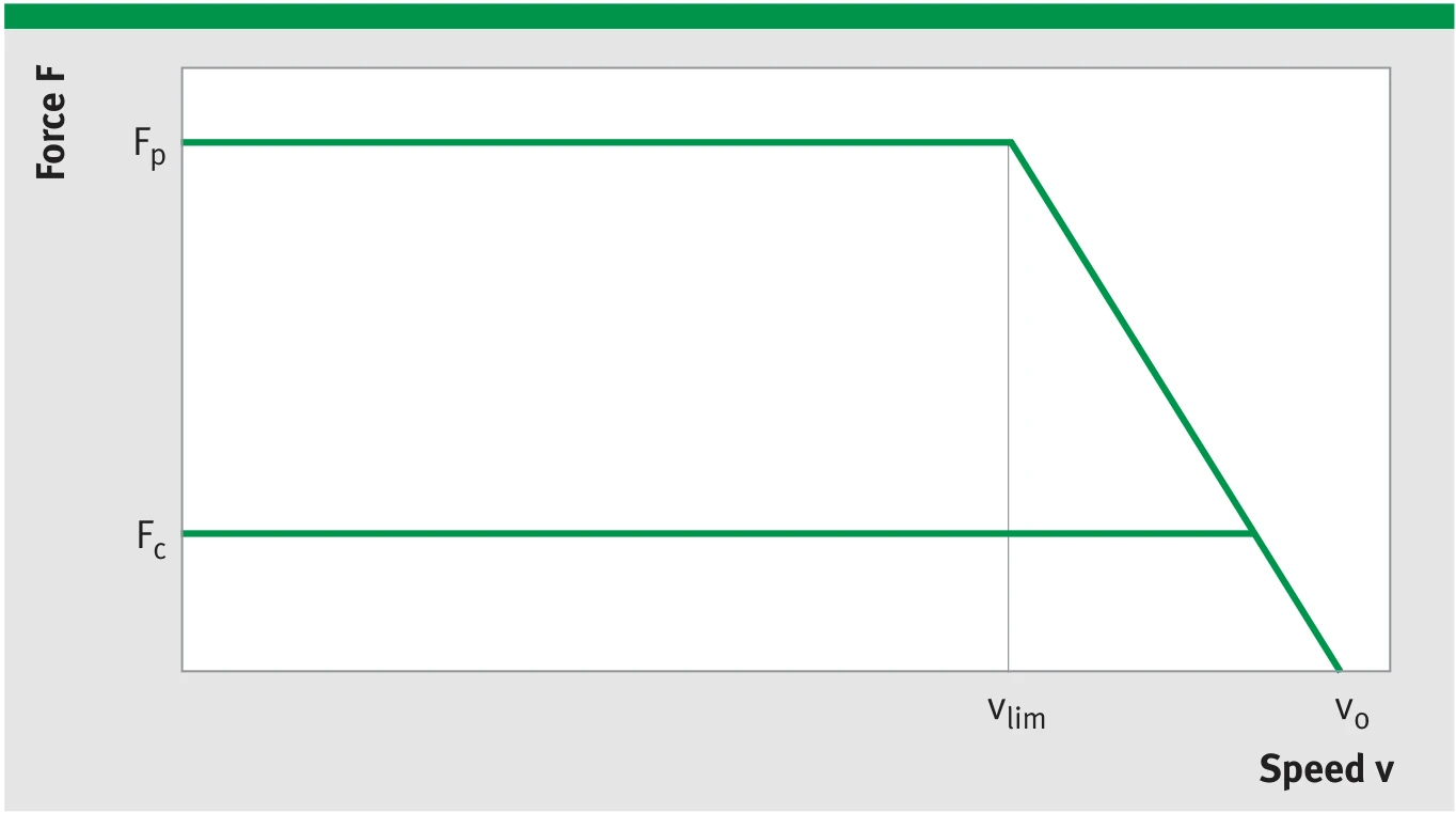
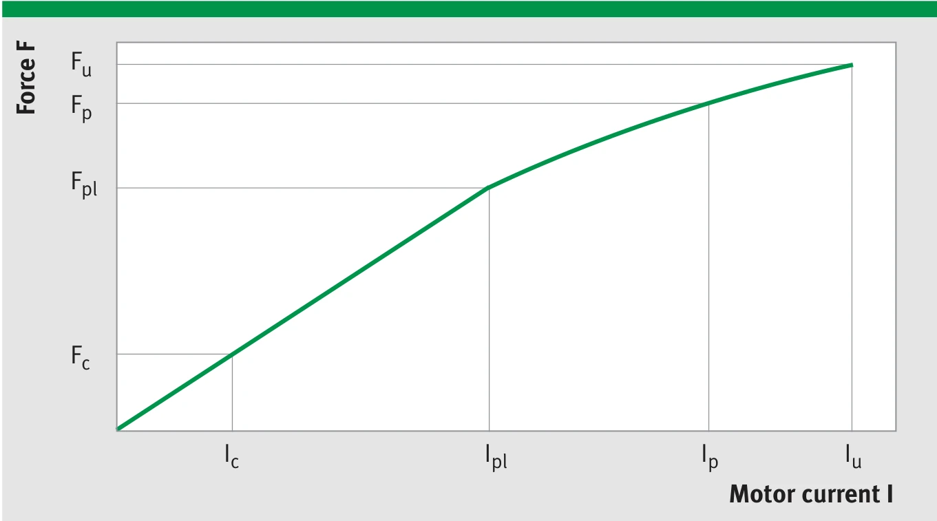
L1A-3P-100-B Force-Speed (F-v) and Force-Current (F-I) characteristic curves
The achievable speed limit depends on operating voltage (UDCL) and current (force). The diagram shows the idealised envelope with the key operating points at peak current (Fp, vlim) and at idle (Fo, v0).
Technical Data III — Winding Data
| Parameter | Symbol | Unit | 100-25-WM | 100-50-WM | 100-75-WM |
|---|---|---|---|---|---|
| Force constant | kf | N/Arms | 17.4 | 34.9 | 52.1 |
| Back EMF constant (phase-to-phase) | ku | V/(m/s) | 14.3 | 28.5 | 42.6 |
| Limit speed (Ip, UDCL=300 VDC) | vlim | m/s | 13.0 | 6.0 | 3.8 |
| Limit speed (Ip, UDCL=600 VDC) | vlim | m/s | 27.3 | 13.2 | 8.6 |
| Resistance (phase-to-phase, 25 °C) | R25 | Ω | 2.40 | 3.49 | 4.58 |
| Inductance (phase-to-phase) | L | mH | 6.60 | 13.20 | 19.80 |
| Limit current | Iu | Arms | 14.3 | 14.3 | 14.3 |
| Peak current (saturation) | Ip | Arms | 11.4 | 11.4 | 11.4 |
| Peak current (linear) | Ipl | Arms | 6.7 | 6.7 | 6.7 |
| Continuous current | Ic | Arms | 2.1 | 2.3 | 2.2 |
| Permissible temperature (at sensor) | θ | °C | 100 | 100 | 100 |
| Maximum DC bus voltage | UDCL | V | 600 | 600 | 600 |
L1A-3P-100-B winding parameter characteristic
Note: The winding variant WM (standard) described above is suitable for moderately dynamic performance requirements. The winding variants WL and WH suitable for lower and higher dynamic performance requirements are available upon request. The integrated temperature sensors do not display the exact winding temperature. Depending on current load, the winding temperature may be up to approx. 30 K higher.
L1A-3P-200-B Technical Data
Technical Data I — Mechanical Parameters
| Parameter | Symbol | Unit | 200-25-WM | 200-50-WM | 200-75-WM |
|---|---|---|---|---|---|
| Primary Part | |||||
| Length | L1 | mm | 208 | 208 | 208 |
| Width | B1 | mm | 57 | 82 | 107 |
| Height | H1 | mm | 20.2 | 20.2 | 20.2 |
| Mass | m1 | kg | 0.9 | 1.6 | 2.2 |
| M5 threaded holes (L x W) | — | — | 6 x 1 | 6 x 2 | 6 x 2 |
| M5 thread pitch/length | nl x c1 | mm | 5 x 31.5 | 5 x 31.5 | 5 x 31.5 |
| M5 thread pitch/width | nb x b1 | mm | — | 1 x 30 | 1 x 55 |
| Motor cable diameter | dK | mm | 7.3 | 7.3 | 7.3 |
| Secondary Part — Through Hole (variant 2) | |||||
| Width | B2 | mm | 50 | 80 | 100 |
| Mass (length 38/152) | m2 | kg/unit | 0.11/0.44 | 0.19/0.76 | 0.24/0.96 |
| Magnetic base height | h2 | mm | 6 | 6 | 6 |
| Height | H2 | mm | 10 | 10 | 10 |
| Through hole (screw M5 DIN 6912) | b3 | mm | 37 | 62 | 87 |
| Secondary Part — Threaded Hole (variant 1) | |||||
| Width | B2 | mm | 30 | 50 | 80 |
| Mass (length 38/152) | m2 | kg/unit | 0.076/0.30 | 0.13/0.52 | 0.21/0.84 |
| Magnetic base height | h2 | mm | 6 | 6 | 6 |
| Height | H2 | mm | 10 | 10 | 10 |
| M5 threaded hole (from below) | b2 | mm | 15 | 30 | 55 |
| Installation Dimensions | |||||
| Total height PRIM + SEK | H | mm | 31 -0.1 | 31 -0.1 | 31 -0.1 |
| Mechanical air gap | d | mm | approx. 0.8 | approx. 0.8 | approx. 0.8 |
| Maximum width | B | mm | 57 | 82 | 107 |
| Secondary part length (38 mm grid) | L2 | mm | L1 + stroke | L1 + stroke | L1 + stroke |
| Cable length | LK | mm | ≈ 1000 | ≈ 1000 | ≈ 1000 |
Technical Data II — Electrical Performance Data
| Parameter | Symbol | Unit | 200-25-WM | 200-50-WM | 200-75-WM |
|---|---|---|---|---|---|
| Limit force (Iu) | Fu | N | 398 | 796 | 1188 |
| Peak force (saturation) (Ip) | Fp | N | 338 | 677 | 1010 |
| Peak force (linear) (Ipl) | Fpl | N | 235 | 470 | 701 |
| Continuous force (Ic) | Fc | N | 72 | 148 | 225 |
| Power loss (Ip, 25 °C) | Plp | W | 938 | 1364 | 1774 |
| Power loss (Ipl, 25 °C) | Plpl | W | 327 | 475 | 618 |
| Power loss (Ic, 25 °C) | Plc | W | 31 | 47 | 64 |
| Motor constant (25 °C) | km | N/√W | 13.0 | 21.6 | 28.2 |
| Damping constant (short circuit) | kd | N/(m/s) | 169 | 465 | 796 |
| Electrical time constant | τel | ms | 2.99 | 4.11 | 4.74 |
| Attraction force | Fa | N | 1128 | 2256 | 3383 |
| Force ripple (typical cogging) | Fr | N | 7 | 14 | 21 |
| Pole pair width | 2τp | mm | 38 | 38 | 38 |

L1A-3P-200-B Force-Speed (F-v) and Force-Current (F-I) characteristic curves
The achievable speed limit depends on operating voltage (UDCL) and current (force). The diagram shows the idealised envelope with the key operating points at peak current (Fp, vlim) and at idle (Fo, v0).
Technical Data III — Winding Data
| Parameter | Symbol | Unit | 200-25-WM | 200-50-WM | 200-75-WM |
|---|---|---|---|---|---|
| Force constant | kf | N/Arms | 34.9 | 69.8 | 75.0 |
| Back EMF constant (phase-to-phase) | ku | V/(m/s) | 28.5 | 57.1 | 61.4 |
| Limit speed (Ip, UDCL=300 VDC) | vlim | m/s | 5.5 | 2.3 | 2.2 |
| Limit speed (Ip, UDCL=600 VDC) | vlim | m/s | 12.7 | 5.9 | 5.6 |
| Resistance (phase-to-phase, 25 °C) | R25 | Ω | 4.80 | 6.98 | 4.72 |
| Inductance (phase-to-phase) | L | mH | 14.35 | 28.70 | 22.36 |
| Limit current | Iu | Arms | 14.3 | 14.3 | 19.8 |
| Peak current (saturation) | Ip | Arms | 11.4 | 11.4 | 15.8 |
| Peak current (linear) | Ipl | Arms | 6.7 | 6.7 | 9.3 |
| Continuous current | Ic | Arms | 2.1 | 2.1 | 3.0 |
| Permissible temperature (at sensor) | θ | °C | 100 | 100 | 100 |
| Maximum DC bus voltage | UDCL | V | 600 | 600 | 600 |

L1A-3P-200-B winding parameter characteristic
Note: The winding variant WM (standard) described above is suitable for moderately dynamic performance requirements. The winding variants WL and WH suitable for lower and higher dynamic performance requirements are available upon request. The integrated temperature sensors do not display the exact winding temperature. Depending on current load, the winding temperature may be up to approx. 30 K higher.
Subject to modification without previous notice.
General tolerance: all values ±5%
Tolerance for attraction force and force ripple: ±10%
Tolerance for resistance and inductance: ±10%
The size specified for the air gap d is an auxiliary dimension and may fluctuate. The only technically relevant dimension is the specified overall installation height H, which must be complied with.
A stainless steel cover can be ordered separately for the secondary parts (not included in the standard equipment).