LDDS-032-C Technical Data
System Data
| Parameter | Symbol | Unit | LDDS-032-C |
|---|---|---|---|
| Width | W | mm | 100 (without connectors) 166 (with connectors) |
| Length | L | mm | 157 (without cover screw heads) 163 (with cover screw heads) |
| Height | H | mm | 120 |
| Total mass | m | kg | 10.5 |
| Moving mass | mmov | kg | 1.4 |
| Maximum payload | m | kg | 3.5 |
| Maximum stroke | s | mm | ±5.5 (between limit positions) ±8.7 (between hard stops) |
| Maximum speed | vmax | m/s | 0.6 (with max. payload) 1.1 (without max. payload) |
| Maximum acceleration | amax | m/s² | 80 (with max. payload) 300 (without max. payload) |
System Components
| Parameter | Symbol | Unit | LDDS-032-C |
|---|---|---|---|
| Encoder type | Optic incremental | ||
| Resolution | µm | 20 | |
| Reference mark | 1 (in the centre of measuring length) | ||
| Accuracy (at 3 sigma) | µm | ±5 | |
| Repeat accuracy | µm | ±2 | |
| Interface | Sinusoidal signal 1 Vpp (sin/cos) | ||
| Reference sensor type (S1) | NC MOS relay (max. 40 VDC at 0.1 A) | ||
| Limit sensor type (S2) | NC MOS relay (max. 40 VDC at 0.1 A) |
Motor Data
| Parameter | Symbol | Unit | LDDS-032-C |
|---|---|---|---|
| Motor type | 2x L1B-3P-100x50 (linear motor with iron core) | ||
| Ultimate force (1 s) at Iu | Fu | N | 726 |
| Peak force (saturation range) at Ip | Fp | N | 640 |
| Peak force (linear range) at Ipl | Fpl | N | 478 |
| Continuous force at Ic | Fc | N | 222 |
| Cogging (ripple force) | Fr | N | 24 |
| Ultimate current (1 s) | Iu | Arms | 17.8 |
| Peak current (saturation range, 3 s) | Ip | Arms | 14.2 |
| Peak current (linear range) | Ipl | Arms | 8.0 |
| Continuous current | Ic | Arms | 3.8 |
| Power loss at Fp | Plp | W | 910 |
| Power loss at Fpl | Plpl | W | 286 |
| Power loss at Fc | Plc | W | 62 |
| Motor constant (25°C) | km | N/√W | 20.0 |
| Back EMF constant, phase to phase | ku | V/(m/s) | 49.1 |
| Electrical resistance, phase to phase (25°C) | R25 | Ω | 3.0 |
| Electrical inductance | L | mH | 21.65 |
| Electrical time constant | τel | ms | 7.23 |
| Magnetic period | 2τp | mm | 38 |
| Maximum winding temperature | ϑ | °C | 100 |
| Maximum DC link voltage | UDCL | V | 600 |
Moving Direction of the Linear Direct Drive System
When the motor is powered according to the circuit diagram, the push-rod is moving into the housing.
Thermal Motor Protection
| Sensor | Sensor Type |
|---|---|
| Temperature sensor 1 | PTC (6x, serial connected) |
| Temperature sensor 2 | Pt1000 temperature sensor (1x) |
| Description | Specification |
|---|---|
| PTC type | Nominal switch temperature TN: 100°C TN −5 K: RPTC < 550 Ω TN +5 K: RPTC > 1.33 kΩ |
| Pt1000 type | Temperature run linear: 3.851 Ω/K 0°C: RPt1000 ≈ 1000 Ω |
A safe electrical separation is not implemented in case of a direct connection of PTC or Pt1000 to the servo controller. The PTC is required to protect the motor against overtemperature. The Pt1000 temperature sensor provides temperature monitoring.
Motor Terminal Assignment
Connector type: 9 way M17 plug connector · Internal wye connection
| Pin | Signal |
|---|---|
| 1 | Phase U |
| 2 | Phase V |
| 3 | Phase W |
| PE | PE |
| A | PTC (6x in series, all phases) |
| B | PTC (6x in series, all phases) |
| C | (empty) |
| D | + Temperature sensor (any phase) |
| E | − Temperature sensor (any phase) |
| Case | Shield |
Measuring System
Connector type: 17 way M17 plug connector
| Pin | Signal |
|---|---|
| 1 | +5 V sense |
| 2 | S1 (ref) |
| 3 | (empty) |
| 4 | GND sense |
| 5 | S2 (LIM +/−) |
| 6 | S1/S2 supply |
| 7 | +5 V |
| 8 | (empty) |
| 9 | (empty) |
| 10 | GND |
| 11 | (empty) |
| 12 | U2+ |
| 13 | U2− |
| 14 | U0+ |
| 15 | U1+ |
| 16 | U1− |
| 17 | U0− |
| Case | Shield |
If using cable lengths of 5 m or more, stress peaks can appear at the motor clamps because of harmonic waves and reflections. These can exceed the DC link voltage and may damage the motor winding insulation. In this case, additional filters must be used. For details, refer to the operating manual.
Drawing
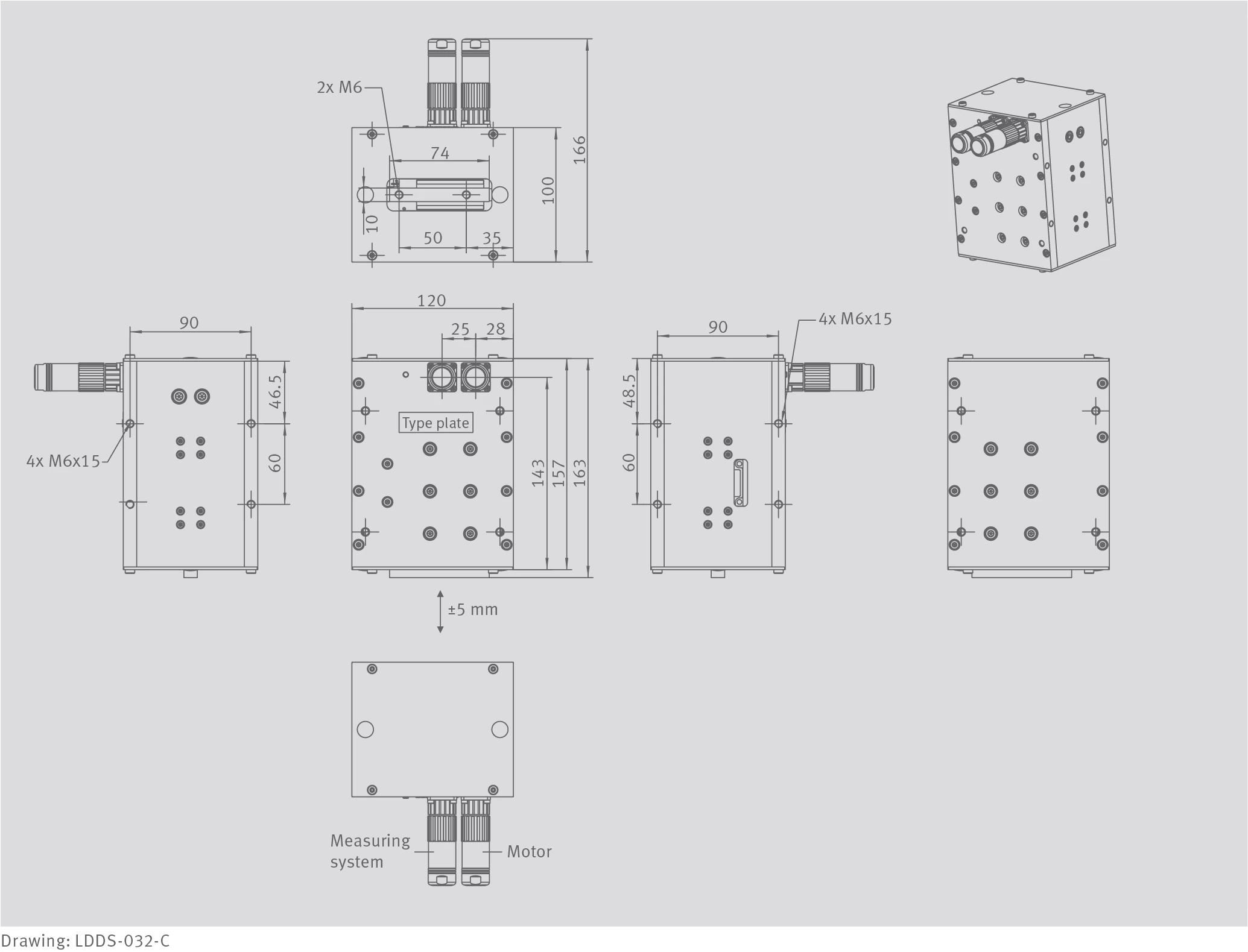
Drawing: LDDS-032-C