不同的應用領域需要線性導軌和循環單元的不同特性。
產品選擇時需要考慮多種參數和因素。以下詳細說明這些關鍵考量。
保持器長度 K ⇄ 滾動元件數 R_A 換算
Cage Length K ⇄ Number of Rolling Elements R_A
行程 H 與導軌長度 L 比例檢查器
Stroke / Guideway Length Ratio Checker
行程 H 與導軌長度 L 的關係
Relationship between stroke H and length of the guideway L
行程 < 400 mm
If the stroke is below 400 mm
行程 > 400 mm
If the stroke is above 400 mm
| L | = 線性導軌長度 (mm) Length of the linear guideway in mm |
| H | = 可能行程 (mm) Possible Stroke in mm |
計算保持器長度 K
Calculating the cage length K
對稱行程
If the stroke is symmetrical
非對稱行程
If the stroke is asymmetrical
H > H₁ + H₂
H₁₂ = H₁ + H₂
| K | = 保持器長度 (mm) Cage length in mm |
| L | = 線性導軌長度 (mm) Length of the linear guideway in mm |
| H | = 可能行程 (mm) Possible Stroke in mm |
| H₁ | = 大部分行程 = H/2 (mm) Large partial stroke in mm = H/2 |
| H₂ | = 小部分行程 = H/2 (mm) Small partial stroke in mm = H/2 |
| H₁₂ | = 有效部分行程 (mm) Effective partial stroke in mm |
計算每個保持器的滾動元件數量 (RA)
Calculating the number of rolling elements (RA) per cage
a) 保持器類型:KBN, AA-RF, AC, AK, EE, SHW, HW
For cage types KBN, AA-RF, AC, AK, EE, SHW, HW

或
b) 保持器類型:KBS
For cage type KBS

或
| K | = 保持器長度 (mm) Cage length in mm | t | = 保持器分度 (mm) cage division in mm |
| RA | = 每個保持器的總可用滾動元件數 Total available rolling element per cage | Kt | = 負載長度 (mm) Load-bearing length in mm |
| w | = 從保持器起始到第一個滾動元件中心的距離 (mm) Distance from cage start to the middle of the first rolling element in mm | tz | = KBS 保持器中間段的長度 (mm) Length of the middle section for the KBS cage |
保持器長度 K 與平均導軌間距 Q 的關係
The relationship between the cage length K and the average guideway spacing Q
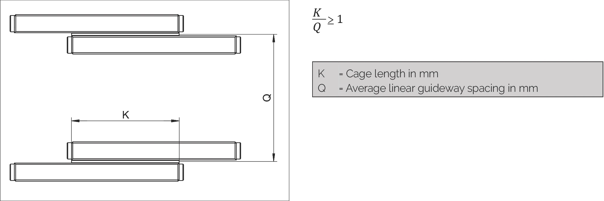
| K | = 保持器長度 (mm) Cage length in mm |
| Q | = 平均線性導軌間距 (mm) Average linear guideway spacing in mm |
超行程保持器的最大允許安裝比例
The maximum permissible installation ratio in the case of overrunning cages

當需要在長導軌軌道上移動短工作台時,超行程保持器是一種有效的解決方案。在這種情況下, 導軌的短軌必須配備圓形導入部(特殊版本 EG,參見第 7.3 章),以使超行程保持器產生的脈動盡可能小。
最大允許安裝比例 L : L₁
Maximum permitted installation ratios L to L₁:
| 固定式導軌 for fixed guideways | 1 : 2 |
| 疊置式導軌 for laid on guideways | 1 : 4 |
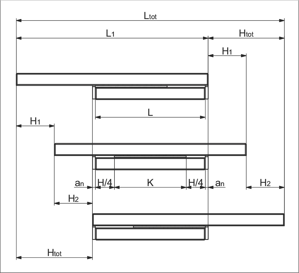
線性導軌的安裝變體
Installation variants for linear guideways
線性導軌有四種安裝變體。各種線性導軌也可以使用端件形式的刮水器 (a₁)*。 在這四種情況下,會產生以下長度比率:
變體 1
- 等長軌道
- 對稱/非對稱行程

a) 無端螺絲、端件和刮水器端件
Without end screws, end pieces, and end pieces with wipers
b) 配備端螺絲、端件和刮水器端件**
For end screws, end pieces, and end pieces with wipers**
變體 2
- 等長軌道
- 單向行程

a) 無端螺絲、端件和刮水器端件
Without end screws, end pieces, and end pieces with wipers
b) 配備端螺絲、端件和刮水器端件**
For end screws, end pieces, and end pieces with wipers**
變體 3
- 不等長軌道
- 對稱/非對稱行程
- 短軌附加
a) 無端螺絲、端件和刮水器端件
Without end screws, end pieces, and end pieces with wipers
b) 配備端螺絲、端件和刮水器端件**
For end screws, end pieces, and end pieces with wipers**
變體 4
- 不等長軌道
- 對稱/非對稱行程
- 長軌附加

a) 無端螺絲、端件和刮水器端件
Without end screws, end pieces, and end pieces with wipers
b) 配備端螺絲、端件和刮水器端件**
For end screws, end pieces, and end pieces with wipers**
參數說明
| K | = 保持器長度 (mm) Cage length in mm | H | = 可能行程 (mm) Possible stroke in mm |
| H₁ | = 大部分行程 = H/2 (mm) Large partial stroke in mm = H/2 | H₂ | = 小部分行程 ≤ H/2 (mm) Small partial stroke in mm ≤ H/2 |
| Htot | = 有效部分行程 (mm) Effective partial stroke in mm | H12 | = 總部分行程 = H1 + H2 (mm) Total partial stroke in mm = H1 + H2 |
| L | = 導軌長度 (mm) Length in mm | L₁ | = 長軌長度 (mm) Length in mm |
| Ltot | = 總長度 (mm) Total length in mm | an | = 端件厚度 (mm) Thickness of the end piece in mm |
* a₁ 端螺絲、端件和刮水器端件,見第 5 章
** 刮水器可能會影響線性導軌的運行特性